Connections – Vaisala HMT100 User Manual
Page 22
User's Guide ______________________________________________________________________
22 __________________________________________________________________ M210701EN-D
Connections
0505-179
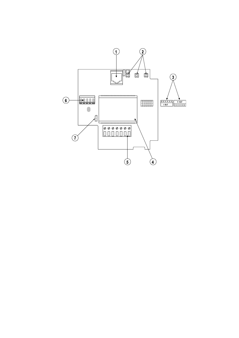
Figure 9
HMT100 Connection Board
The following numbers refer to Figure 9 above:
1 =
Service
port
2 =
Adjustment
buttons
3
=
Jumpers for selecting voltage or current output
(not user adjustable)
4 =
Optional
LCD
5
=
Field wire terminals
6
=
Connector for HMP100 Humidity Probe
7
=
Display backlight jumper (only in voltage output version);
factory setting: backlight ON)
1.
Open the transmitter cover by taking out the cover screws.
2.
Insert the power supply wires and the signal wires through the
cable bushing in the bottom of the transmitter.
3.
Connect the wires as indicated in Figure 10 and in Table 3 on page
23. Note that you must wire the transmitter according to the type of
transmitter (specified at order time as 2-wire current output or 3-
wire voltage output).