Vaisala HM70 User Manual
Page 43
Chapter 9 ______________________________________ Calibration and Adjustment of Transmitters
VAISALA _______________________________________________________________________ 41
−
Select
Settings
, press
−
Select
Measurement settings,
press
−
Select
RH scale: 4...20 mA
or
0...20 mA
, press
ON
−
To return to the basic display, press
EXIT
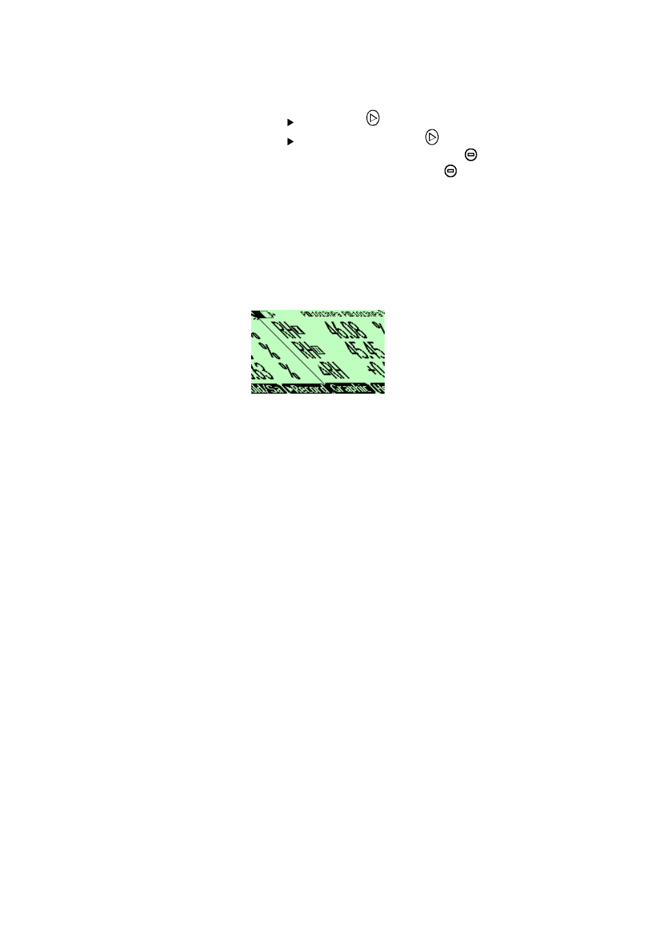
5.
Now the reading of the transmitter is shown on the first or
middle row of the display, depending on the connector port to
which the calibration cable is connected. Value of the port I is
shown on the upper row of the display and the value of the
port II on the lower row of the display. Difference of the
readings is shown in the lowest row.
6.
Ensure that the probes are located in the same conditions. You
can have an optional probe holder for the HMP76 probe to
attach the probe next to the probe of HMD60/70 or HMD20/30
(order code for the probe holder: HM36915).
7.
Wait until the readings have stabilized (can take up to 20
minutes). If the difference between the humidity readings is less
than 2 % RH, there is no immediate need for adjustment.
8.
Adjust the transmitters reading to correspond the HM70
reference probe by turning the small screw on the modules on
the transmitter's mother board marked with
RH offset
/
RH gain
. If
the RH reading is < 65 %, turn the
RH offset
screw and if the RH
reading is >65 %, turn the
RH gain
screw. Turning to the
clockwise direction increases the reading, turning to opposite
direction decreases the reading.
Do not breathe towards the transmitter probes when adjusting
the reading.
9.
When the transmitter reading is equal with the HM70 reference
probe's reading, adjustment is done.
10.
Switch off HM70 and detach the cable from the transmitter and
the HM70 indicator.