Mounting sensors and enclosure, Weatherhawk ® 5 – WeatherHawk Inversion - Wireless User Manual
Page 8
WeatherHawk
®
5
815 W. 1800 N. Logan, Utah 84321-1784, Email: [email protected]
Copyright © 2004, 2010
Toll free in USA: 866-670-5982, International: 435-750-1802, FAX: 435-750-1749
Printed November 2010
If you are installing the CM375 mast at the same time as the Inversion System, go to Section 2.2.
The following tables list the equipment that is included with an inversion system for mounting on a pre-existing
tower/pole. It is advisable to inventory the system for completeness before beginning installation. Power supply
options are listed in Appendix A.
Inversion System Common Components
Equipment Description
Part Number
Quantity
Temperature Probe, Top
21414
1
Temperature/RH Probe, Bottom
21415
1
6-Plate Gill Solar Radiation Shield
4020
2
Lead Acid Battery, 12 Volt, 2.9 AHr
18860
1
Wind Sensor Set w/Mounting Hardware
21413
1
Cable Tie, Black, UV Resistant
17592
12
Direct Connect System Specific Components
Equipment Description
Part #
Qty
Enclosure Assembly – 232
21379
1
RS – 232 Optical Isolator, 9 – pin
21429
1
RS – 232 Optical Isolator Power
Supply
21435
1
RS – 232 Data Cable
10873
1
Wireless System Specific Components
Equipment Description
Part #
Qty
Enclosure Assembly – 916
21380
1
900MHz Spread Spectrum
Radio
18102
1
900MHz Dipole Antenna
15970
1
Radio Power Adapter
15966
1
The top temperature probe and the bottom temperature/RH probe should already be mounted inside the solar radiation
shields. The following table lists the hand tools necessary to install a WeatherHawk Temperature Inversion System.
Hand Tools List
½ inch wrench
Compass
#2 Phillips Screwdriver
Post Level
Small Wire Cutters
Tape Measure
2.1.1. Mounting Sensors and Enclosure
1.
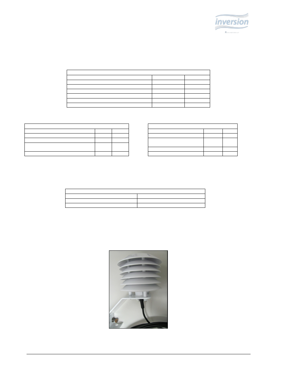
Mount the top Temperature Sensor (pn. 21414) at a height of 30 feet on the south side of the tower/pole. Place the
provided U-bolt in the side holes of the radiation shield (see Figure 5) and tighten the nuts.
Figure 5: Temperature
radiation shield
(pn 21414).