Available outputs, Contact specifications – DAVIS Alarm Output Module User Manual
Page 6
Page 6
Alarm Output Module
Available Outputs
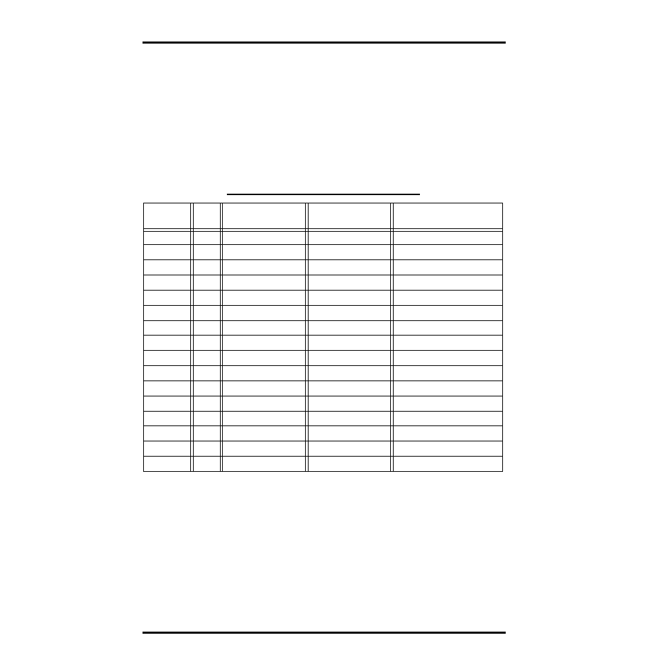
The AOM provides four output contacts which may be selected from the condi-
tions listed below. Each output (except time, daily ET, and the “User” outputs)
remains active as longs as the alarm condition exists. The time and daily ET
outputs remain active for one minute. The “User” outputs must be activated
and deactivated by the user via the WeatherLink Software for that station. Also
shown in the table below are the pin assignments for each of the three consoles.
The “Radio Power” output is used to control switching of power to radio when
in the power-conserving mode (see “AOM Connections for Radio Power-Con-
serving Options” on page 12).
Contact Specifications
The “contact” closure is provided by a photo-coupled MOS device. Because it
is a solid-state device, it is not subject, as long as the load conditions are within
specification, to arcing and contact-welding as are mechanical relays. The Con-
trol Output and Status contacts are rated as follows:
A
LARM
S
IGNAL
P
IN
A
SSIGNMENTS
(J3)
A
LARM
O
UTPUT
J3
P
IN
G
RO
W
EATHER
C
ONSOLE
E
NERGY
EM
C
ONSOLE
H
EALTH
EM
C
ONSOLE
16
Time
Time
Air Temp-Low
15
Daily ET
Temp-Hum Index
Air Temp-High
14
Dew Point
Dew Point
Inside Temp-Low
13
Radio Power
Radio Power
Inside Temp-High
12
Hum-Low
Air Temp-Low
Outside Hum-Low
11
Hum-High
Air Temp-High
Outside Hum-High
10
Air Temp-Low
Hum-Low
Inside Hum-Low
9
Air Temp-High
Hum-High
Inside Hum-High
8
Soil Temp-Low
Wind Chill
UV Dose
7
Soil Temp-High
Wind Speed
Outside Temp-Hum Index
6
User 1
User 1
Wind Speed
5
Temp-Hum Index
Daily Rain
Temp-Hum-Sun-Wind Index
4
Wind Chill
Not Used
Daily Rain
3
Wind Speed
Not Used
Inside Temp-Hum Index
2
User 2
User 2
Wind Chill
1
Daily Rain
Barometer
UV Index
Nominal Load Voltage: 28V AC or 48V DC, Maximum
Peak Voltage:
±100 V, Maximum
Load Current
±300 mA, Maximum at 77° F (25° C),
derated to 150mA at 176° F (80° C)
ON Resistance
4 Ohms, Maximum