ADT Security Services Unimode 9600 User Manual
Page 36
,QVWDOODWLRQ
2SWLRQDO 0RGXOHV DQG 'HYLFHV
8QLPRGH 31 &
0RGXOH ,QVWDOODWLRQ RQ %5.7
7KH IROORZLQJ PRGXOHV FDQ EH LQVWDOOHG LQVLGH WKH 8QLPRGH FDELQHW XVLQJ WKH
%5.7 8QLYHUVDO %UDFNHW
✓ ADT-UDACT Digital Alarm Communicator/Transmitter - installs at standoff
location (A)
✓ ADT-ACM-8R Annunciator Control Module (Relay) - installs at standoff
location (A)
5HIHU WR WKH DSSURSULDWH PRGXOH PDQXDO IRU GHWDLOHG LQIRUPDWLRQ RQ PRGXOH RSHUDWLRQ
DQG ZLULQJ
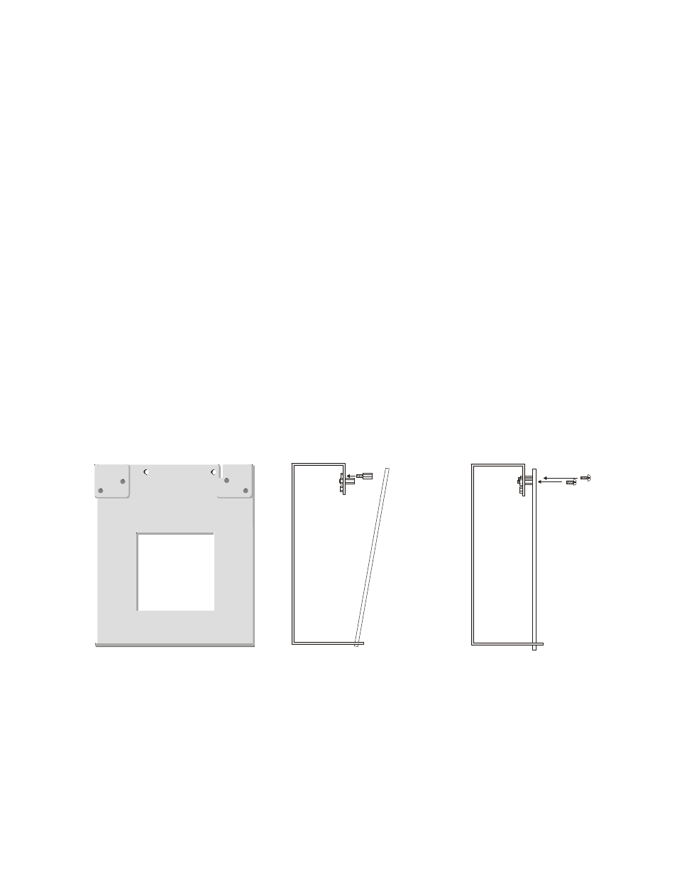
1. Install the two supplied standoffs in location (A) as indicated in Step 1 of the
following illustration
2. Position the module bottom in the slot located in the bottom of the BRKT-9600 as
indicated in Step 2 of the following illustration
3. Secure the module to the standoffs installed in the top of the BRKT-9600 with two
mounting screws as indicated in Step 3 of the following illustration
4. Refer to the appropriate module manual for detailed information on wiring the
module for power, communication, etc.
5. Install a maximum of two 12 Amp Hour batteries with the orientation illustrated in
Figure 2.13. Larger batteries require a separate UL listed battery box
1RWH 'R QRW EULQJ ZLULQJ RU FRQGXLW LQWR WKH ERWWRP RI WKH FDELQHW IRU WKLV
DSSOLFDWLRQ
Figure 2.14 BRKT-9600 Module Installation Steps
Step 1
Step 2
Step 3
(A)
(A)
Slot
module
module
BRKT-9600
BRKT-9600
BRKT-9600
mounting
screws
standoffs
96brc
ks
d.c
dr
9600brkt.cdr