4 controls and indicators, Product description controls and indicators, Figure 1.2 membrane/display panel – ADT Security Services Unimode 9600 User Manual
Page 16
Product Description
Controls and Indicators
16
Unimode 9600 PN 51336:C 11/06/01
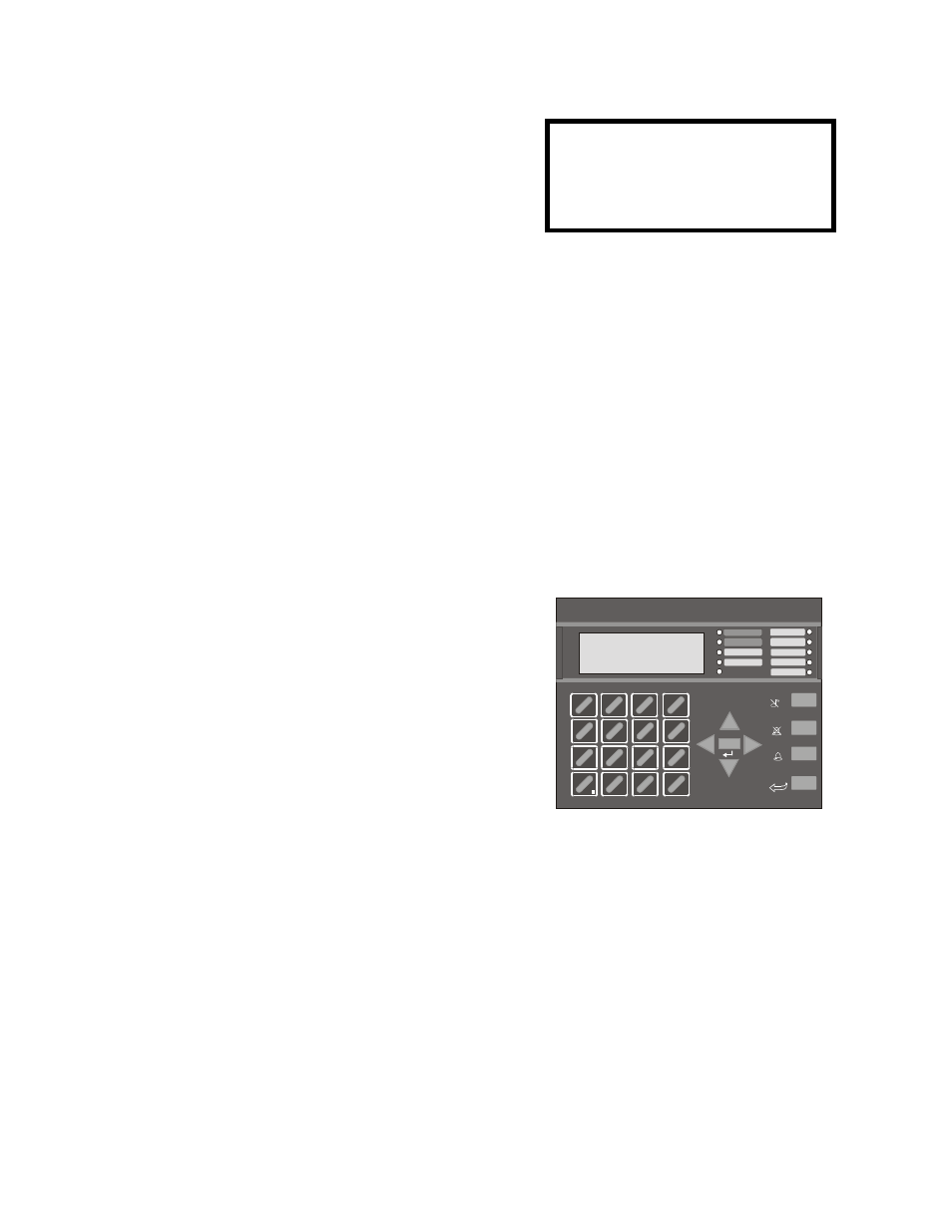
1.4 Controls and Indicators
LCD Display
The FACP uses an 80-character (4 lines
X 20 characters) high viewing angle
LCD display. The display includes a
long life LED backlight that remains
illuminated. If AC power is lost and the
system is not in alarm, the LED
backlight will turn off to conserve batteries.
LED Indicators
LED indicators are provided to annunciate the following conditions:
• AC Power (green)
• Fire Alarm (red)
• Supervisory (yellow)
• Trouble (yellow)
• Maintenance/presignal (yellow)
• Alarm Silenced signals (yellow)
• Disabled (yellow)
• Battery fault (yellow)
• Ground fault (yellow)
Key Panel
Mounted on the main circuit board, the key panel includes a window for the LCD display
and LED indicators as listed above. The key panel, which is visible with the cabinet door
closed, has 25 keys, including a 16 key alpha-numeric pad similar to a telephone keypad.
Function keys:
• Acknowledge/Step
• Alarm Silence
• Drill
• Reset (lamp test)
Service/program keys:
• Keys labeled 1 to 9
• * key
• # key
• 0 (recall) key
• 1st Event key
• Clear key
• Escape key
• Mode key
• Four cursor keys (up, down, left and right)
• Enter key
Local Piezo Sounder
A piezo sounder provides separate and distinct pulse rates for alarm, trouble and
supervisory conditions.
SYSTEM ALL NORMAL
10:00A 010101
1
4
*
2
5
0
3
6
#
1
st
EVENT
ABC
DEF
GHI
JKL
MNO
PRS
TUV
WXY
QZ
-/.
CLR
7
8
9
ESC
ENTER
RECALL
ACK/STEP
ALARM
SILENCE
DRILL
HOLD 2 SEC
RESET
MODE
MAINTENANCE
ALARM
SILENCED
DISABLED
BATTERY
GROUND
SUPERVISORY
TROUBLE
AC POWER
FIRE ALARM
Figure 1.2 Membrane/Display Panel
9600kypd.c
dr