Lokar GM Hi-Tech Kickdown Kit User Manual
Gm hi-tech kickdown kit installation instructions, Fig. 1 fig. 2
Building American Quality… With A Lifetime Warranty!
General Installation Notes:
Please read these instructions completely before beginning the instal-
lation. If you have any questions please call.
Before beginning the installation, disconnect the negative battery
cable and use wheel chocks to block the vehicle's wheels.
We recommend using anti-seize lubricant on all aluminum threads.
NOTE: This Lokar Kickdown Kit is designed to be installed with a Lokar
Carburetor Bracket and Springs, part # SRK-4000 (not included, available
separately). The Lokar Kickdown Cable is designed to be cut-to-fit.
Refer to Figs. 1, 2 and 3 for the component names.
Step 1: Remove the cable end stop, kickdown throttle body fitting, and
kickdown cable adjuster from the new Lokar kickdown cable. If you
have the braided stainless steel housing, make sure you
DO NOT remove
the ferrule from the cable housing if the cable housing is braided
stainless steel. Leave the kickdown mounting bracket on the kickdown
cable adjuster. Remove the inner wire from the cable housing.
Step 2: From the engine end of the kickdown cable housing, install the tube
hold down clip onto the cable housing with the lip pointed downwards,
and slide it down to the trans tube at the end of the cable housing.
Temporarily install the cable housing into the transmission without the
o-ring(s) and inner wire. Loosely install the bolt for the tube hold down
clip, to keep the cable housing from accidentally coming out of the
transmission.
Fig. 4
Note: TH200 and TH350 transmissions could have come with either
a standard or a metric bolt for the trans tube hold down clip. For
those applications, we have included both a standard 1/4"-20 and a
metric M6 bolt and lock washer for the trans tube hold down clip. The
standard 1/4" – 20 bolt has a rounded button head, and the metric
M6 bolt has a square-shouldered socket head.
Fig. 2 The TH200-4R,
700-R4, and 4L60 will only have a metric bolt and washer in the kit.
Step 3: If the throttle cable has already been installed, disconnect the
throttle cable from the carburetor. If the engine already has a Lokar
Carburetor Bracket installed, remove the throttle cable adjuster. Leave
the carburetor bracket in place. If the engine does not have a Lokar
Carburetor Bracket already installed, install one now, following the
installation instructions that were provided with the Lokar Carburetor
Bracket.
TOLL FREE 1-877-469-7440 • [email protected] • www.lokar.com
®
GM Hi-Tech Kickdown Kit Installation Instructions
For TH350, 700-R4, TH200, TH200-4R, and 4L60
For TH350, 700-R4, TH200, TH200-4R, and 4L60
INS0003 Rev. 08/05/2014
Page 1
© 2005 Lokar, Inc.
GM Hi-Tech Kickdown Kit Installation Instructions
Step 4: The kickdown mounting bracket mounts onto
the back side of the Lokar Carburetor Bracket
(not included). The throttle cable adjuster will
pass through the top hole in both the new
kickdown mounting bracket
AND the carburetor
bracket. Position the kickdown mounting bracket
behind the carburetor bracket so that the 5/16"
diameter holes at the top of both brackets are
aligned, the small 3/16" diameter holes near the
center of the two brackets are aligned, and the
kickdown cable adjuster is offset towards the left
side of the vehicle.
Attach the kickdown mounting bracket to the
carburetor bracket using the supplied
#8-32 x 1/2" button head bolt and nylock nut
through the small 3/16" diameter center holes
in both brackets, but do not tighten yet. Insert
the throttle cable adjuster (with the rear nut still
installed) from the rear through the top holes
in both brackets. Position it so that the bracket
is roughly centered in the threaded part of the
cable adjuster. Install the front adjuster nut.
Tighten the throttle cable adjuster nuts, the
button head bolt and nut, and the kickdown
cable adjuster nuts.
Fig. 5
Step 5: Route the cable housing up to the kickdown
cable adjuster.
Make sure that the inner wire
is removed from the cable housing. If the
cable housing is braided stainless steel, slide
the ferrule down the housing towards the
transmission, away from the end that is being
cut.
DO NOT remove the ferrule from the braided
stainless steel housing! If the cable housing is
black universal, remove the ferrule.
Measure the distance between the kickdown
cable adjuster and the tube hold down clip.
Add 1" to the measurement and cut the cable
housing to that length.
If the kickdown cable has a braided stainless
steel housing, wrap tape around the area to
be cut and use an abrasive cutoff saw or fine-
toothed hacksaw. If the kickdown cable has a
black universal housing, cut the cable housing
with heavy duty 8” diagonal cutting pliers or
a hacksaw. Lokar recommends Klein brand
Diagonal Cutting Pliers, # D2000-28 available
at The Home Depot or through W. W. Graingers,
Part # 4A838.
After cutting the cable housing, put the ferrule
back in place at the end of the cable housing.
Insert the cable housing and ferrule into the
kickdown cable adjuster.
#8-32 x 1/2" Button Head
Bolt with Nylock Nut
Kickdown
Mounting
Bracket
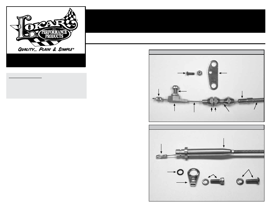
Cable End
Stop
Kickdown Throttle
Body Fitting
Cable
End
Trans Tube
O-Ring
Tube Hold
Down Clip
M6 Metric
Socket Head
Bolt and Lock
Washer
1/4"–20 Standard
Button Head Bolt
and Lock Washer
Inner
Wire
Adjuster
Nuts
Kickdown
Cable Adjuster
Cable
Housing
Hex Carb
Fitting
Ferrule
Fig. 1
Fig. 2
Carburetor End
Transmission End, TH200 & TH350