Lokar Cable Operated Shifter GM User Manual
Page 2
Page 2
© 2007 Lokar, Inc.
Fig. 4
Fig. 5
Step 1: If your vehicle already has a shifter of any type installed, disconnect all shifter linkage and remove
the shifter and its related hardware (neutral safety switch, back-up light switch, etc.).
Step 2: Determine exactly where you want the shifter to be located. The shifter may be mounted either on
top of the floor or underneath the floor.
NOTE: For vehicles that had a floor shifter previously, determine if the existing hole in the floor
will be adequate for mounting and operation of the Lokar shifter. If not, the floor will need to
be modified.
If you are mounting the shifter on top of the floor, you will need a slot in the floor for the quad
arm to pass through. If you are mounting the shifter underneath the floor, you will also need an
opening for the floor mount mounting bracket.
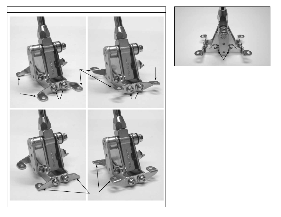
Step 3: There are two pairs of floor mount tabs in the shifter kit. How they are arranged when installed on
the shifter depends on if you are mounting the shifter above or below the floor, and on the size
of the shifter boot ring if you are installing a shifter boot and ring directly on the floor. If you are
using the Lokar rectangular shifter boot and ring, at least two of the floor mount tabs (both front or
both rear) must be installed pointing inward.
See
Fig. 4 to determine how the floor mount tabs need to be positioned for your particular
application.
Attach the floor mount tabs to the floor mount mounting bracket as shown in
Fig. 4 with the
5/16"-24 x 1/2" button head bolts and lock washers. Leave the bolts loose enough so that
adjustments can be made later during the installation.
Step 4: Make sure the two 5/16"-24 x 3/8" socket head bolts that are in the curved, slotted holes in the
left side of the floor mount mounting bracket are tight. Place the shifter in the desired location.
Make sure the shifter will not interfere with the dash when in Park, or with the seat when in low
gear. The shifter assembly may be tilted forward or backward if needed by loosening the two
socket head bolts that are in the curved, slotted holes in the left side of the floor mount mounting
bracket. Retighten the socket head bolts in the curved, slotted holes once you have the shifter
assembly at the angle you want.
Fig. 5
Note: If you ever disassemble the shifter assembly, be sure that the 5/16"-24 x 3/8” button head
bolts and lock washers are put back into the curved, slotted holes in the floor mount mounting
bracket. Installing longer bolts will prevent the shifter from operating.
Push the floor mount tabs flush against the floor, and mark the center of the bolt holes in the floor
mount tabs onto the floor. Center punch the marks, and drill four 5/16" diameter holes.
Step 5: Attach the shifter to the floor using four 5/16"-24 x 1/2" button head bolts and nylock jam nuts.
Once the shifter is mounted to the floor, tighten the floor mount tab to floor mount mounting
bracket bolts.
Step 6: Make sure the shifter is in the Park position. Check the position of the quad lever. It should be
pointing to about the 5:00 position. If it is not, loosen the set screw in the top of the quad lever
with a 1/8" Allen wrench and slide the quad lever off of the shaft. Reposition it on the shaft at
approximately the 5:00 position, and retighten the set screw.
Fig. 6
Determine which one of the quad arms included in the kit should be used to mount to the quad
lever. There are three different options to choose from: straight, 1-1/4" offset and 2-1/2" offset.
NOTE: For the best results, use the quad arm with the least amount of offset that will still clear the
transmission and work for your application.
Install the quad arm onto the quad lever using the two 1/4"-28 x 5/8" button head bolts and
nylock jam nuts.
Fig. 7
Above Floor Installation
Below Floor Installation
Floor
Mount
Tabs
Floor
Mount
Tab
Floor
Mount
Tabs
5/16"-24 x 1/2" Button Head
Bolts with Lock Washers
Floor Mount Tabs turned inward
for Shifter Boot Ring clearance
5/16"-24 x 1/2" Button Head
Bolts with Lock Washers
5/16"-24 x 3/8" Button Head Bolts and
Lock Washers in curved, slotted holes