Wiring diagram – Flex-a-Lite 52007 Camaro Radiator Kit Fits 1967-1969 First Generation Chevrolet Camaro User Manual
Page 3
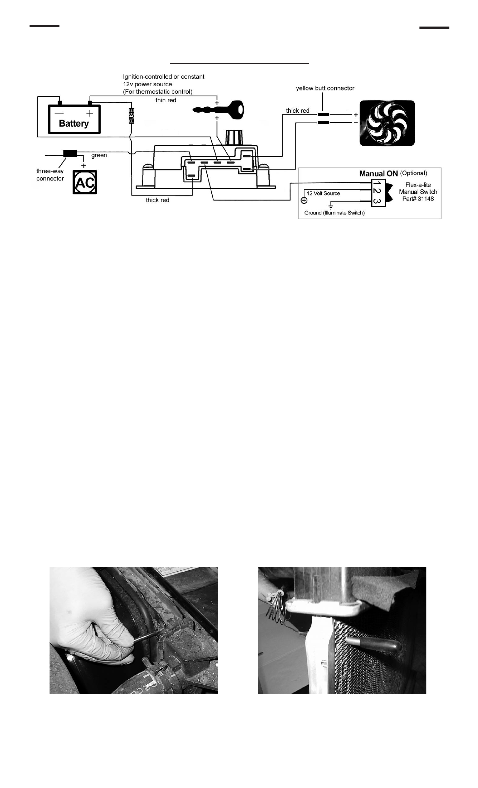
Wiring the Fan: Radiator and Fan Combo #52187 only
Wiring Diagram
colored
black
thick
black
thick black
Connect the motor wires to the control module (Red wire to the “M+” terminal and black wire to the “M-”
terminal).
Use the large diameter red (10 AWG) wire to run power directly from the battery positive (+) terminal to
the “B” terminal on the control module. Connect the fuse holder in-line with this wire, as shown, but do not
insert the fuse yet. Use the yellow female, ring, and butt connectors provided.
Use the large diameter black (10 AWG) wire to run from the negative (-) battery terminal to the “G” terminal
on the control module. Use the yellow female connector and ring connector provided.
Use the small diameter red wire (14 AWG) to connect the “+” terminal on the control module to a positive
power source.
NOTE: Attaching this wire to an ignition-controlled source will shut off the fan when
the engine is turned off. Attach this wire to an uninterrupted (always hot) power source to allow the fan
to continue running after th e engine is shut off. Use the blue female connector and fuse taps (included) if
necessary.
If the vehicle is equipped with air conditioning, a
mandatory connection is needed between the “C” terminal
on the control module and the positive wire that triggers the A/C compressor. Using a voltmeter, determine
which wire coming from the compressor is the positive trigger wire. Use the included 3-way connector and
small diameter green wire (14 AWG) to tap into this wire and send a signal to the fan control module. The
fan will cycle on and off with the A/C clutch when the A/C is turned on.
(Optional) For manual switch operation, use Flex-a-lite p/n 31148. Connect the switch as shown on the
wiring diagram (previous page). Connect the “M” terminal on the control module to the “1” terminal on the
switch. Connect the “2” terminal on the switch to a positive 12v power source. Connect terminal “3” on
the switch to a good ground (for switch illumination).
NOTE: To prevent thermostatic activation (if only
manual switch operation is desired), omit the lead to the “+” terminal of the control box. “B”, “G”,
“M+” and “M-” must remain connected. If not using a Flex-a-lite manual switch, do not connect a
ground wire to the switch!
Use the zip ties provided to secure the wires and prevent them from interfering with fan blades, belts, and
pulleys in the engine compartment. Insert the fuse provided.
Locate the inlet hose from the engine to the radiator. Remove the black insulator cap from the temperature
probe then insert the temp. probe through the radiator fins near the inlet hose. Reinstall the black insulator
cap.
1.
2.
3.
4.
5.
6.
7.
8.
Install temp. probe near inlet hose...
then replace the insulator cap.
Rev. 02-09-11 99187 Page 3 of 4