Flex-a-Lite 52184 Ford 97-04 Mustang Rad/Fan Combo User Manual
Flex-a-Lite For the car
1
#52104 F
or
d 97-07 Mustang R
adia
tor
#52184 F
or
d 97-04 Mustang R
ad/F
an C
omb
o
Fits MOST F
or
d Mustangs
, 1997-2004
(N
ot
e: A
ut
oma
tic tr
ansmissions ma
y r
equir
e an
auxiliar
y tr
ansmission oil c
ooler par
t # 4110M4
. V
ehicle
mo
dels ma
y v
ar
y; r
evie
w the instr
uc
tions and
comp
onen
ts f
or c
ompa
tibilit
y with y
our v
ehicle prior t
o
installa
tion)
Remo
ve R
adia
tor and E
lec
tric F
an
1. M
ake sur
e eng
ine is c
ool
.
2. Disc
onnec
t nega
tiv
e (-) ba
tt
er
y cable fr
om ba
tt
er
y.
3. L
oosen dr
ain v
alv
e on passenger lo
w
er side with 5/16”
allen wr
ench and dr
ain c
oolan
t.
(F
ig
. 1)
4. F
rom belo
w
, r
emo
ve outlet tube fr
om r
adia
tor
.
5. Undo r
eser
voir tank tubing a
t t
op dr
iv
er side of
radia
tor
.
6. Disc
onnec
t sensor wir
e a
t base of r
eser
voir tank
.
7. R
emo
ve 3 ea. 11mm nuts secur
ing r
eser
voir tank
.
8. Lif
t o
ver
flo
w bottle t
o ac
cess lo
w
er hose clamp
.
Disc
onnec
t hose and r
emo
ve o
ver
flo
w bottle
.
9. R
emo
ve 4 ea. scr
ew clips fr
om plastic panel
sur
rounding hood la
tch. R
emo
ve panel and set aside
.
10. R
emo
ve clip
-on bolts fr
om t
op of r
adia
tor suppor
t.
(F
ig
. 2)
11. R
emo
ve upper r
adia
tor hose and secur
e a
w
ay fr
om
radia
tor
.
12. Undo plug har
ness fr
om elec
tr
ic fan.
13. P
op tr
ee
-clip holding wir
ing har
ness t
o elec
tr
ic fan.
14. R
emo
ve t
op r
adia
tor moun
t br
ackets
.
2
3
Install N
ew F
le
x-a-F
it® R
adia
tor
1.
A
tt
ac
h
lo
w
er
b
ra
ck
et
to
p
as
se
ng
er
s
id
e
of
ra
di
at
or
w
ith
supplied t
-bolts
, w
ashers
, and nuts
. S
et base of br
acket
flush t
o bott
om of r
adia
tor tank
. (F
ig
. 3
)
2.
L
ow
er
ra
di
at
or
a
ss
em
bl
y
in
to
e
ng
in
e
co
m
pa
rt
m
en
t
en
su
rin
g
bo
th
b
ot
to
m
p
os
ts
s
it
fu
lly
w
ith
in
th
e
ru
bb
er
bushings of the v
ehicle r
adia
tor suppor
t.
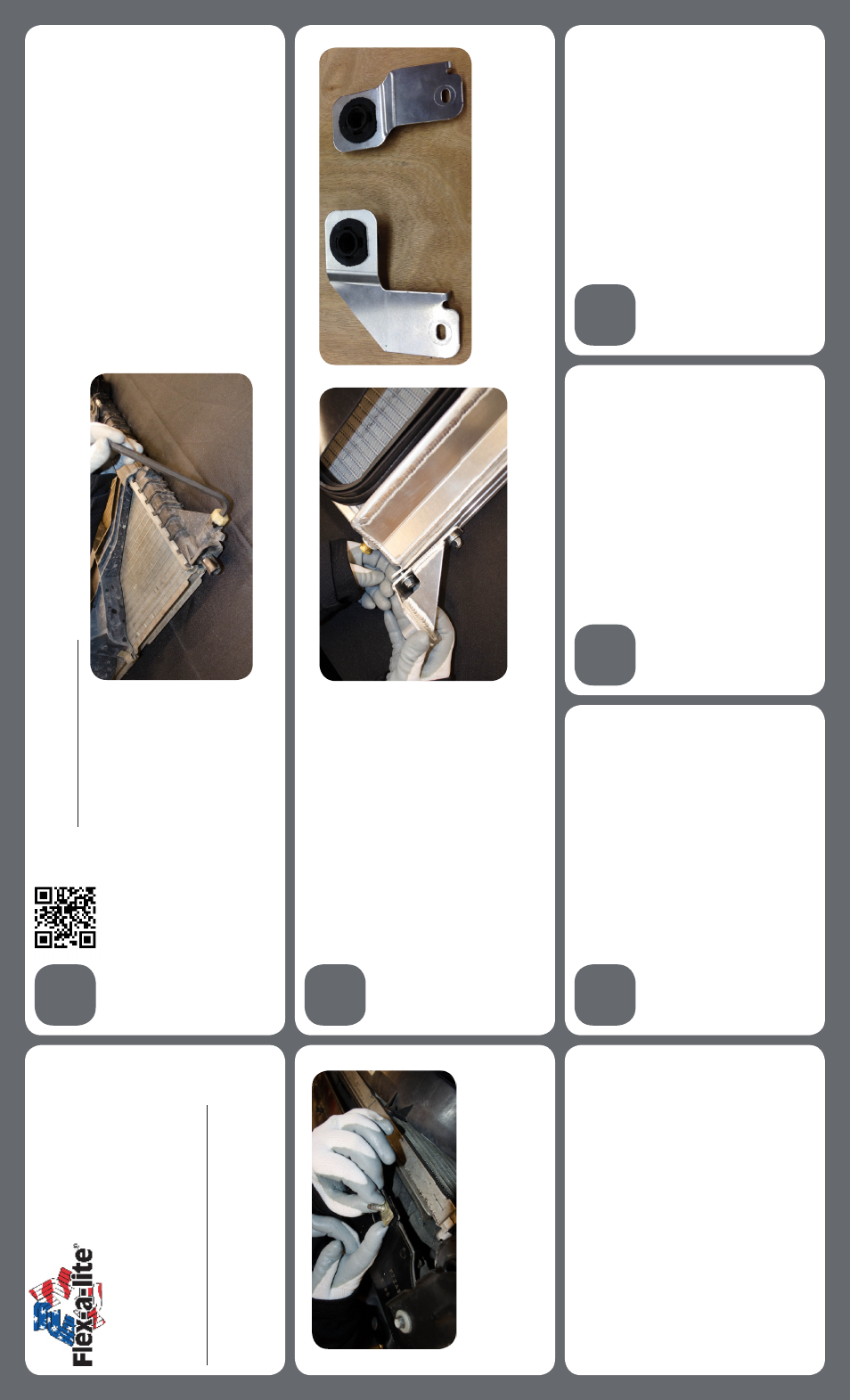
3.
R
em
ov
e
ru
bb
er
g
ro
m
m
et
s
fr
om
fa
ct
or
y
to
p
ra
di
at
or
moun
ting br
ackets and install in
to supplied
replac
emen
t br
ackets
. (F
ig
. 4)
4.
A
tt
ac
h
br
ac
ke
ts
to
ra
di
at
or
a
nd
m
ou
nt
w
ith
fa
ct
or
y
8mm bolts t
o r
adia
tor suppor
t.
97184 R
ev
. 02-05-14
4
5
Fan
W
iring I
nstr
uc
tions
FOLL
OW
THESE INSTRUC
TIONS C
AREFULL
Y
TO A
VOID
D
AM
AGING
THE C
ONTR
OL UNIT
, F
AN MO
TORS AND
YOUR
VEHICLE!
WHEN CRIMPING
WIRES, AL
W
AY
S USE A
QU
ALIT
Y CRIMPING
TOOL (DO NO
T USE PLIERS OR
O
THER DE
VICES).
Con
tr
oller
W
iring
1. U
sing the lar
ge y
ello
w butt c
onnec
tors pr
ovided
, a
ttach
a length of the thick (10 A
WG) r
ed wir
e t
o the c
olor
ed
mot
or wir
e a
t the fan.
2. A
ttach a length of the thick (10 A
WG) black wir
e t
o
the black mot
or wir
es a
t the fan. Onc
e the fan is in plac
e,
these will a
ttach t
o the c
on
tr
ol unit
.
Scan her
e with y
our smar
tphone t
o see a st
ep
-b
y-st
ep install video
or t
ype
http://y
outu
.b
e/LN
mB
-wh2E2I
in
to y
our fa
vor
ite br
ow
ser
15. Lif
t r
adia
tor and fan assembly up and out of eng
ine
ba
y.
NO
TE:
W
at
ch out f
or additional c
oolan
t dr
aining
fr
om r
adia
tor outlet
.
Fig
. 1
Fig
. 2
5. A
ttach and clamp inlet and outlet hose t
o r
adia
tor
.
Fig
. 3
Fig
. 4
Connec
t P
ow
er L
eads
1. D
et
er
mine the length needed t
o run thick r
ed and black
wir
e fr
om the
VSC t
o the ba
tt
er
y t
er
minals and tr
im
appr
opr
ia
tely
.
2. C
rimp a lar
ge y
ello
w r
ing c
onnec
tor t
o one end of each
wir
e and c
onnec
t the black wir
e t
o the nega
tiv
e (-) ba
tt
er
y
ter
minal
, but DO NO
T c
onnec
t the r
ed wir
e y
et!
3. U
sing butt c
onnec
tors
, c
onnec
t the fuse holder pr
ovided
inline with the r
ed wir
e.
VSC M
oun
ting
1. L
oca
te a moun
ting poin
t f
or the
VSC near inlet of the
radia
tor
. T
he c
on
tr
ol unit needs t
o plac
e within 2-f
eet of
radia
tor inlet f
or t
emp
. pr
obe plac
emen
t. On the f
ender
w
ell ne
xt t
o the r
adia
tor ma
y be a c
on
venien
t plac
e.
2. A
ttach the c
on
tr
ol unit with the pr
ovided scr
ew
s.