BMR Suspension TAS012 User Manual
Page 6
6
TAS010 TORQUE ARM CONVERSION INSTALLATION INSTRUCTIONS
TAS012 - 1968-1974 Nova 12 BOLT
Please take note before proceeding with this installation:
• This product may interfere with certain exhaust kits. Exhaust crossovers are not
compatible with this torque arm suspension. In some circumstances, it may be necessary
to fabricate a custom exhaust to insure adequate clearance.
• While not necessary, a heavy duty cast aluminum differential cover is recommended with
this kit. Cast covers are more structural in nature than the stamped steel OE unit and
will distribute the load across the differential, further strengthening the assembly.
• A service lift, while not necessary, is recommended for this installation.
TOOLS REQUIRED:
3/8” and ½” drive ratchets
9/16”, ¾” wrenches
3/8”, 9/16”, ¾” and 1-1/8” sockets
Rubber mallet
Pry-bar
Drill
3/8”
Allen
wrench
Step bit or ½” and ¾” drill bits
Jack
stands
Hydraulic
Jack
Grease gun with synthetic lube
Torque wrench
Welder
(optional)
Plumb
bob
and
tape
measure
INSTALLATION:
This installation is the second part of the torque arm conversion process. It is assumed at this
point that the installer has already installed the BMR Torque Arm and Torque Arm cross-
member using the appropriate instruction sheets. Lift vehicle and support with stands under the
frame, allowing the rear end to hang.
1. Remove the rear wheels/tires.
2. If the vehicle has exhaust installed,
remove it at this time.
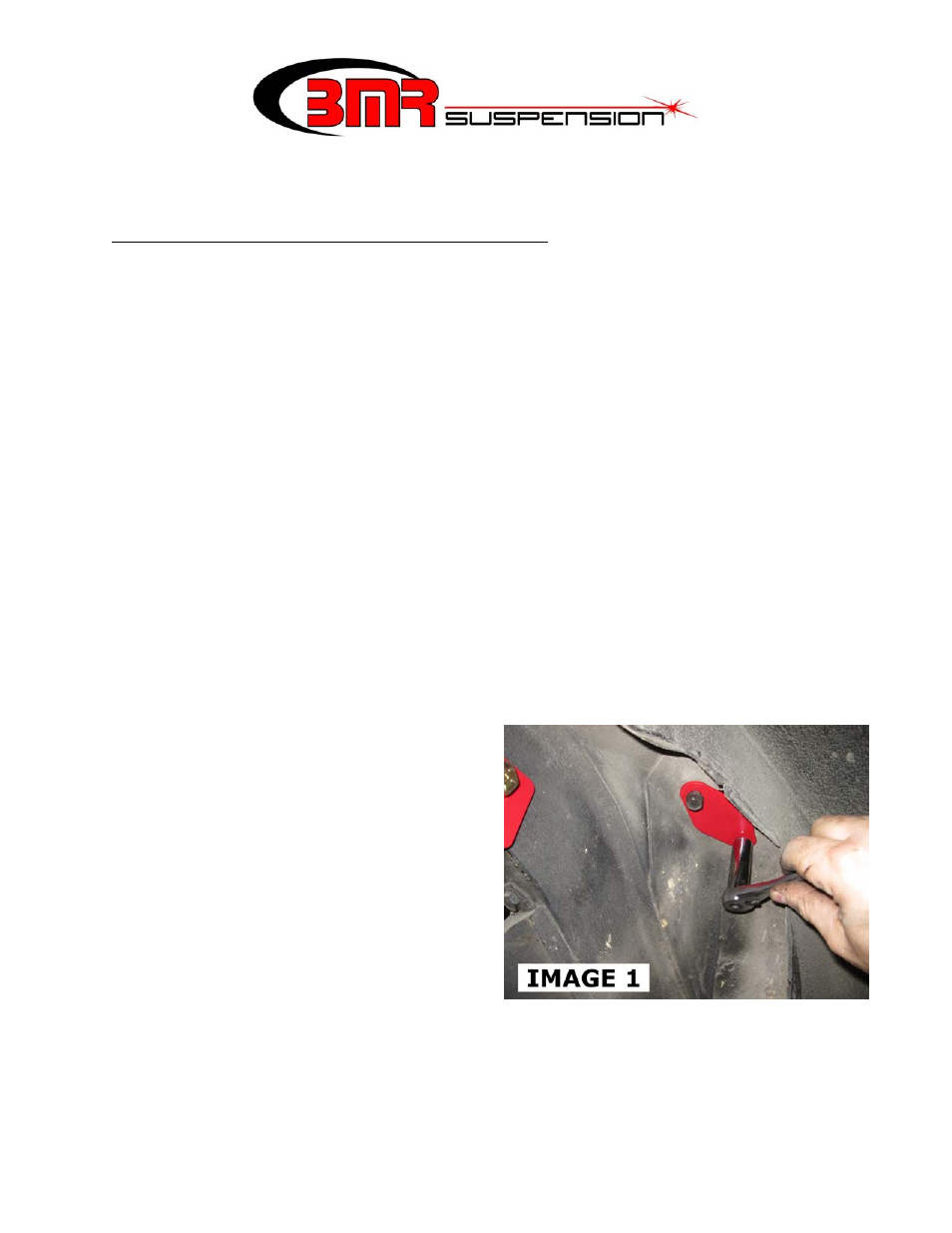
3. Remove the rear shocks. Using the OE
shock bolts, bolt the supplied BMR shock
plates over the factory shock holes as
shown in Image 1.
4. To gain adequate access for the upper
crossmember installation, it is
recommended that the fuel tank be
removed. Drain the tank using a drill
pump or siphon.
5. Support the tank and then remove the two
mounting nuts using a 9/16” deep socket. Pull the tank support straps down, allowing the
tank to be lowered.
6. Lower the tank far enough to access the fuel lines and electrical connectors. Disconnect
and cap the fuel lines. Lower and remove the fuel tank.
7. Support the rear end with jack stands.