BMR Suspension TAS012 User Manual
Page 12
12
(CONTINUED)
30. Place a large diameter washer over the 5/8”
bolt inside the control arm mount and then
thread a nut onto the bolt. Tighten to 80
ft/lbs.
31. Repeat steps 29-31 for the other side.
32. The next few steps involve mounting the
Watts Link. Support the front of the rear end
and loosen the large bolts that attach the
torque arm to the rear differential mounting
plate using a 1-1/8” socket. (Image 18 on
previous page). Using a ¾” wrench and
socket, loosen the (4) ½” cross-bolts on the
torque arm but do not remove them.
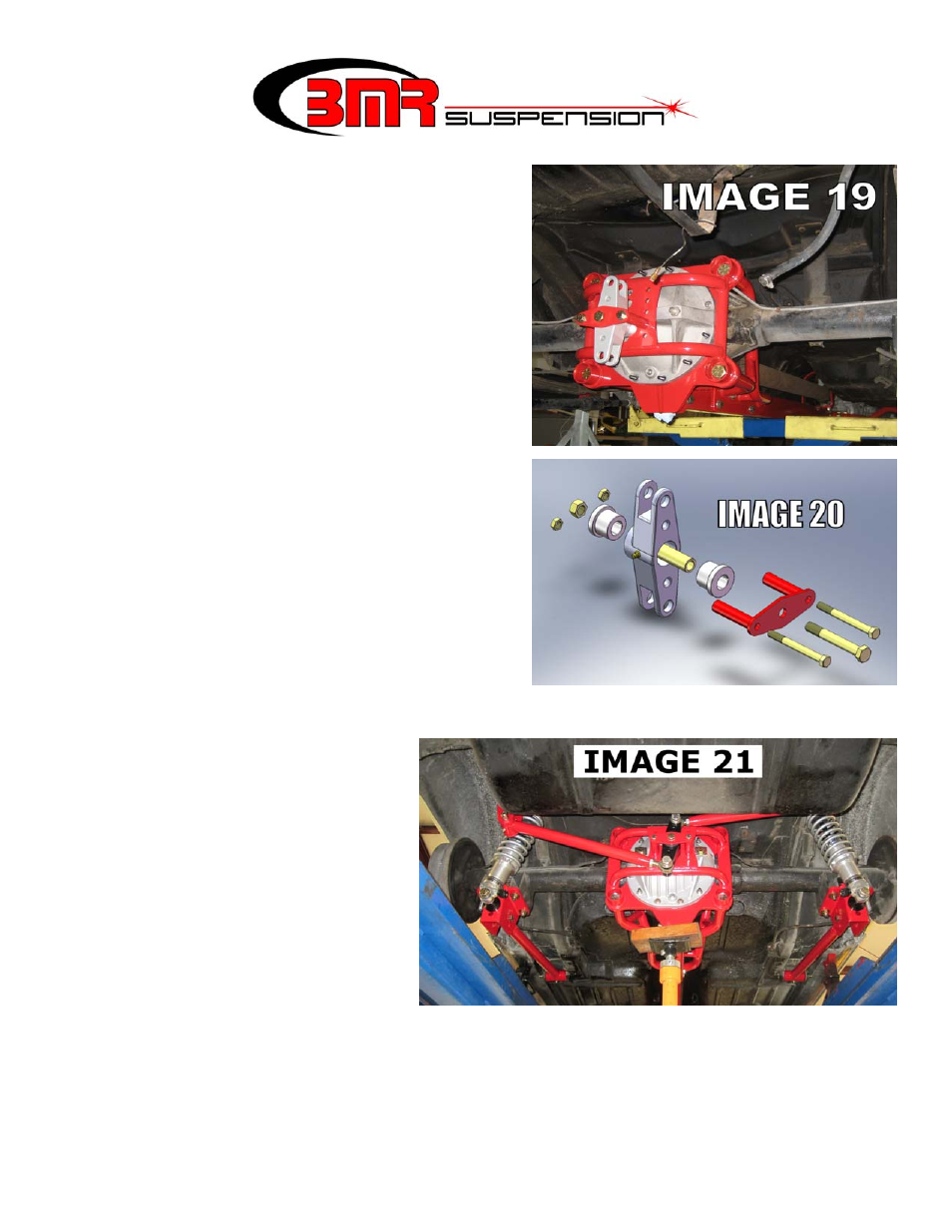
33. Install the BMR Watts Link mount as shown
in Image 19. Re-install and tighten the
mounting bolts to 100 ft/lbs. Tighten the (4)
½” cross-bolts.
34. Locate the billet aluminum Watts pivot, the
reinforcement plate, (2) 3/8” x 3.75” bolts,
and a ½” x 4” bolt. Refer to Image 19 and 20
for a visual representation of these
components. NOTE: If your vehicle will be
setup for a low ride height, choose one of the
lower sets of mounting holes to install the
Watts pivot. For most applications, this is a good starting point. This mounting point
determines the vehicles rear roll center (RC) height. Variances in vehicle center-of-
gravity (CG) height
necessitates multiple mounting
locations for fine tuning RC
height.
35. Tighten the center bolt to 80
ft/lbs. and the smaller outer
bolts to 30 ft/lbs.
36. Before mounting the Watts link
bars, it is necessary to load the
vehicles suspension. Allow the
weight of the vehicle to sit on
the rear end and bounce the car
a few times to settle the
suspension. If the car sits too high or too low, use the provided spanner wrench at this
time to adjust the spring height on the shocks. If it is not possible to adjust the springs
enough to achieve the desired ride height, move the lower shock mounting hole to a
different location. Once the desired spring height is established, tighten the jam collar on
the shock and proceed to the following step.