BMR Suspension TAS012 User Manual
Page 3
3
TORQUE ARM INSTALLATION INSTRUCTIONS (Cont.)
7) Apply another thin bead of RTV onto the BMR torque arm mounting plate at the gasket
mating surface then install the other
supplied gasket.
8) Apply another thin bead of RTV onto the
exposed gasket surface then re-install the
differential cover.
9) Place one of the supplied 5/16” washers
and 5/16” poly-lock nuts onto each stud
and then insert the (8) 5/16” bolts and
washers into the remaining holes. Tighten
all twelve in a star shaped pattern. Snug
each one first then torque them to 20-25
ft/lbs.
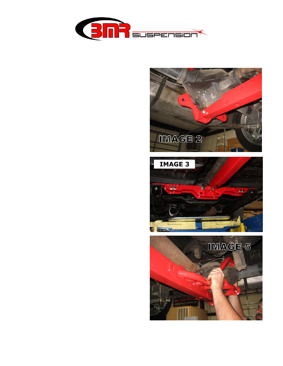
10) Mount the torque arm to the differential
mounting plate using one of the supplied
½” x 3.25” bolts. Place a stainless washer
under the nut and temporarily thread it
finger tight. (See Image 2)
11) Insert the front telescoping bushing into
the torque arm with the grease fitting
pointing downward.
12) Lift the front of the torque arm up until the
bushing hole lines up with the mount on
the torque arm cross-member. Insert the
supplied ½” x 4” bolt, nut and stainless
washer. Tighten to 90 ft/lbs. (Image 3)
13) Using either a 5/8” or ¾” deep socket,
slightly loosen the leaf spring mounts on
the rear end. They should be loose enough
to allow the rear end to rotate slightly.
14) Position one of the support braces up
against the torque arm as shown in Image
5. Place a lock washer over two of the
supplied ¾” x 2” bolts and thread them
into the support brace, through the BMR
differential mounting plate. Leave the
bolts loose.