BMR Suspension XSB002 User Manual
Page 3
3
4
th
GEN F-BODY XTREME REAR ANTI-ROLL BAR INSTALLATION
(Continued)
12. Using the supplied silicone lube, lube the insides of the
polyurethane bushings. Slide the bushings over the BMR
sway bar then install the saddles over the bushings. The
assembled bar should resemble IMAGE 9.
13. Position the supplied u-bolts over the axle. The next step is
easiest if you have a second person but it can be done with a
second set of stands if necessary. Position the bar in place
(center “hump” faces downward) and slide the BMR serrated
axle saddles over the u-bolts then position the ends of the u-
bolts through the sway bar bushing saddles on each side.
Thread the provided 3/8” nuts and flat washers onto the u-
bolts to hold the sway bar in place. NOTE: the BMR
serrated saddles should be mounted as far outward on the
axle as possible to limit side-to-side movement of the sway
bar.
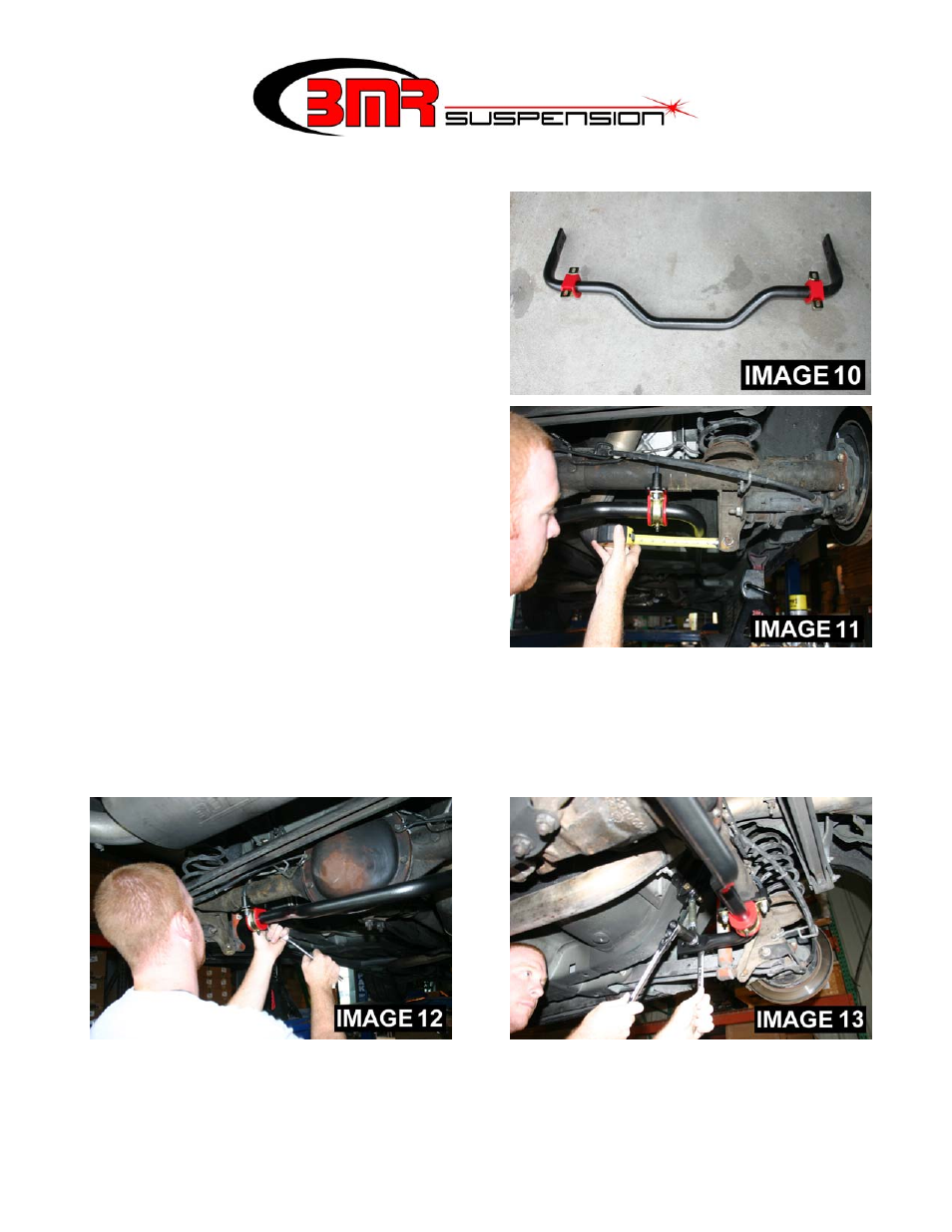
14. Measure each side and adjust the mounting clamps inward or
outward until they are even. IMAGE 11.
15. Once everything is positioned correctly, tighten the u-bolt
nuts snugly, clamping the mounts to the axle. NOTE: do not
over-tighten, it does not take much to sufficiently clamp the
serrated mounts to the housing. A specific torque value can
not be applied to u-bolts. See IMAGE 12.
16. The next step is the installation of the double adjustable end
links. Ride height plays a role in how long your end link will
be. Rotate the sway bar until the lever portions of the bar are
as close to level (in reference to the ground) as possible then
measure the distance from the sway bar mounting hole to the frame mounting hole (if the vehicle is extremely low, you can
use the upper frame mount hole). Adjust your end links to this length (usually 5-5.5”) then install them using the provided
½” x 2.5” bolts. Once both sides are connected, tighten the jam nuts using (2) ¾” wrenches. Tighten the mounting bolts to
85 ft/lbs. See IMAGE 13 below.
17. Lube both bushings with a silicone-based bushing lube.
18. Lower vehicle.