BMR Suspension XSB002 User Manual
Page 2
2
4
th
GEN F-BODY XTREME REAR ANTI-ROLL BAR INSTALLATION
(Continued)
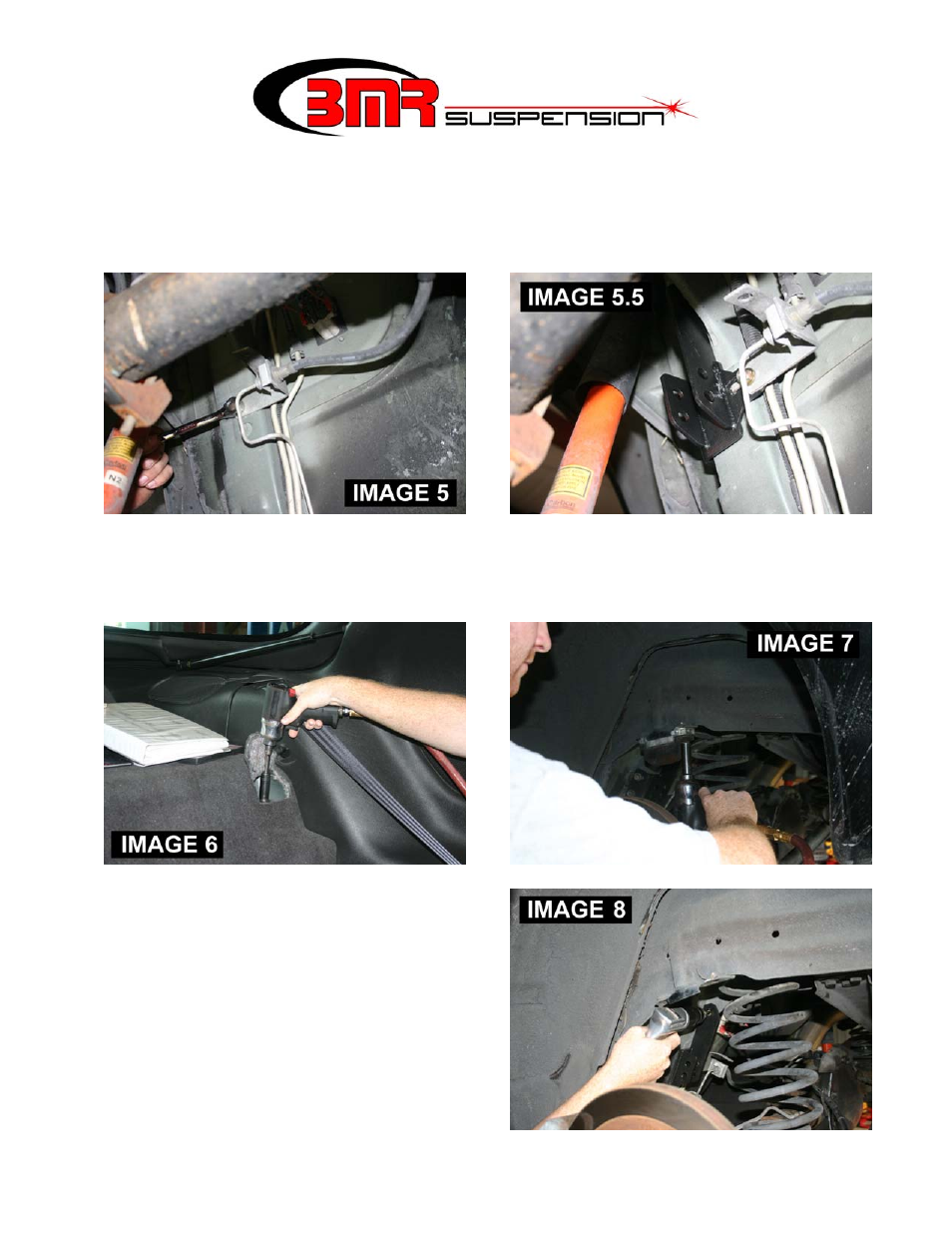
6. Proceed to the Drivers’ side of the vehicle. Unbolt the brake line bracket using a 10mm wrench. (IMAGE 5)
7. Duplicate steps 4-5 on the drivers’ side using the other supplied bracket. Re-position the fuel and brake line bracket to the
BMR mount and bolt it into place using the supplied 5/16” x .75” bolt, washer and lock-nut. NOTE – re-positioning this
bracket may require slight bending of the OE hard lines. (IMAGE 5.5)
8. The next step involves removal of the shocks to gain access to the upper drill points. Fold the rear seat down and pull up the
carpet to gain access to the upper shock stud. Using a 13mm deep socket, remove the upper shock nut (IMAGE 6) then
remove the lower shock nut with a 18mm socket.
9. Using a 13mm socket, remove the bump stops on both sides of the vehicle. (IMAGE 7)
10. Using the upper mounting hole as a drill guide, drill a ½”
hole through the frame web. NOTE: there are (2) ways to do
this. If you have a low-profile or an angle drill, you can drill
from the outside using the hole in the BMR mount as your
guide (this is the easiest method). If you only have a straight
drill, take measurements then drill a small pilot hole from the
inside. Once the pilot hole is drilled, it can be sighted from
the outside then corrected if misaligned with a step bit or die
grinder.
11. Once the hole is drilled, insert the provided ½” x 1.5” bolt,
using the provided aluminum spacer between the BMR
bracket and the drilled frame web. Put a washer and nut onto
the bolt and tighten to 50 ft/lbs. Duplicate steps 10 and 11on
the Drivers side.