American Fibertek CX-6p-PoE User Manual
Page 38
38
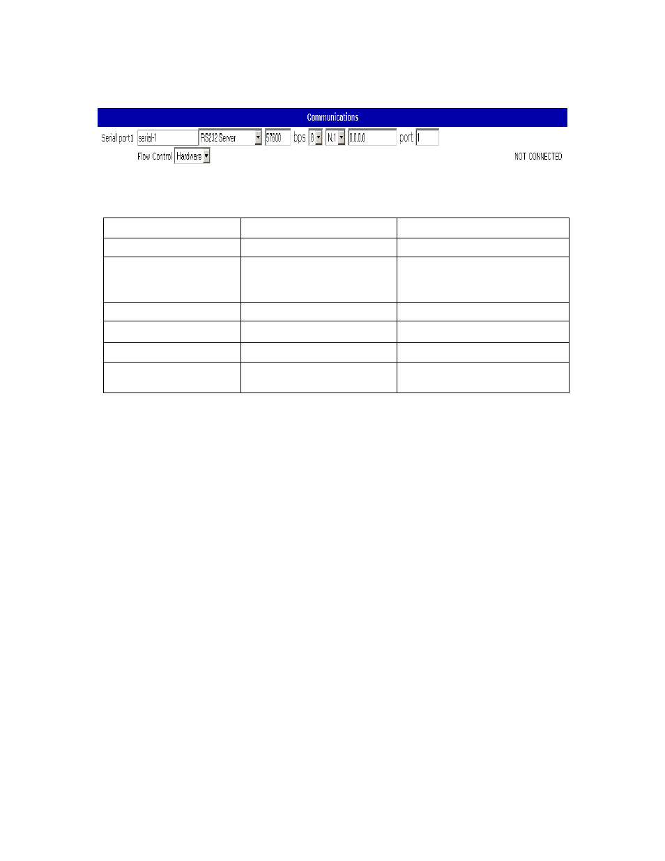
Communications
The Communications screen allows the user to configure the CX-6p-PoE’s serial port.
The serial port has a user-settable text label identifying it for user documentation
purposes. This string can be up to 15 characters long.
The serial mode drop-down menu allows the user to select both the hardware interface
and the software behavior of the serial port.
The software mode can be selected from server or client mode. “Disabled” mode can be
selected to leave a port with no connection to the network.
The hardware baud rate for each port can be selected from 0 to 57600 bps. This
controls the rate at which the hardware port receives and transmits data. It does not
affect the rate at which information is transmitted over the network.
IP address specifies the address of the target CX-6p-PoE on which there will be a port
which this serial port is to link to. This address may be up to 15 characters long and
must be in dotted-quad format. An IP address is required for client mode and must
contain the network IP address of the device the client will connect to. In server mode
the IP address is optional. If an IP address is provided in server mode the server port
will only accept incoming connections from that address.
The port number indicates which port on the target device the CX-6p-PoE will attempt to
connect to in client mode. Note that these numbers refer to the number of the serial port
as indicated on the device and web screen, not the IP port number. This number has no
function in server mode.
The flow control setting is used to control the function of the CTS/RTS pins when the
port is configured in RS232 mode. With flow control set to ‘Hardware’ the RTS output
Setting Default
Value
Range
Name “aux-N” 15
characters
Mode RS232
Server
Disabled
RS232 Server
RS232 Client
Speed 57600
0-57600
IP “0.0.0.0”
15
characters
Port 1-4
1-4
Flow Control
Hardware
Hardware
None