American Fibertek CX-6p-PoE User Manual
Page 10
10
Connecting contacts
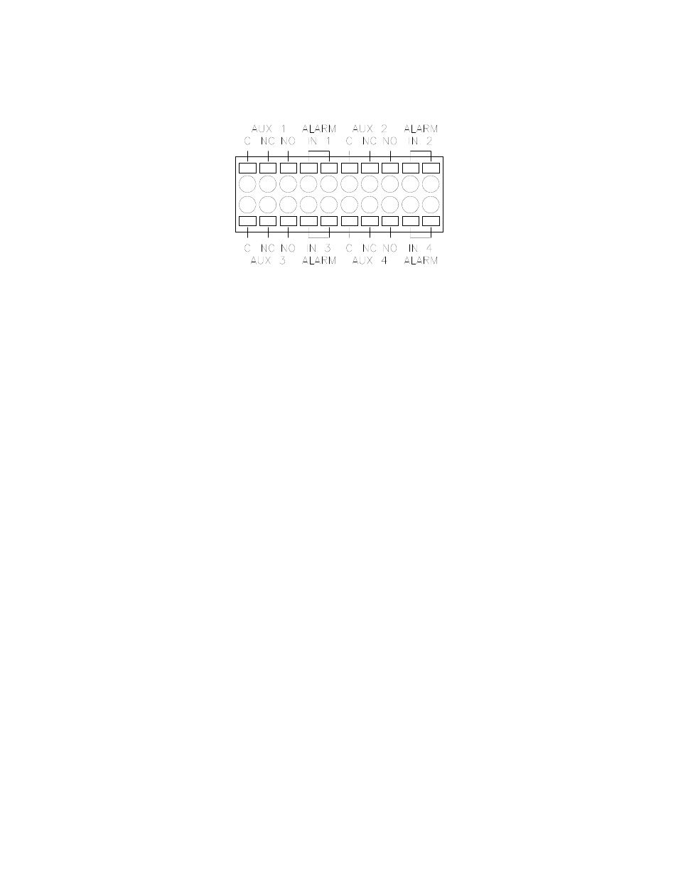
The CX-6p-PoE has a 20-pin connector for 4 alarm inputs and 4 aux contact outputs.
Contact connector – rear view
Each connector point on the block has a tab which is pressed in to insert / release the
wire into the adjacent opening. To make a connection, strip ¼” from the end of a wire,
then while pressing on the small orange tab adjacent insert the wire into the hole. When
the tab is released the wire will be securely held in the hole. To remove the wire, press
the tab again and pull the wire out.
Connecting an alarm input
The 4 alarm input connections are all located on the same terminal block, as indicated
by the above diagram. Each alarm input is a pair of connections which are intended to
be connected to external user equipment.
These terminals are intended to be connected to customer equipment which will make or
break a connection between the two terminals, such as a door open switch or motion
detector contact output. It can be designated through the configuration web page if an
alarm condition will correspond to the connection being made or the connection being
broken.
To connect an alarm source such as a door switch or motion detector to the CX-6p-PoE,
use two wires, 16-28 AWG in size. Strip about ¼” of the insulation from the end of the
wires before inserting them into the terminal block. While pressing in the small orange
tab adjacent insert the wire into the hole. When the tab is released the wire will be held
securely.
Note: the electrical connection to the alarm inputs are to be connected only to isolated
contact closure devices, and must not be directly connected to any external power or
ground source. Directly connecting either terminal of the alarm input to any voltage
source or external ground may damage the CX-6p-PoE.
Connecting a supervised contact
In supervised contact mode a 1K resistor is connected in series with the contact closure.
This resistor should be located at or close to the contact device, so that short circuits
across the contact lines will be detected. A valid contact closure will be registered only
when the resistance across the contact input lines is measured to be nominally 1K ohm.