Power supply leds, Figure 38, Cache status led details – HP MSA 2040 SAN Storage User Manual
Page 80
80
LED descriptions
between the host and the chip on the controller, the controller is not communicating with the chip. To reset
the LED, the controller must be properly power-cycled [see
"Powering on/powering off" (page 27)
].
Cache Status LED details
If the LED is blinking evenly, a cache flush is in progress. When a controller module loses power and write
cache contains data that has not been written to disk, the supercapacitor pack provides backup power to
flush (copy) data from write cache to CompactFlash memory. When cache flush is complete, the cache
transitions into self-refresh mode.
If the LED is blinking momentarily slowly, the cache is in a self-refresh mode. In self-refresh mode, if primary
power is restored before the backup power is depleted (3–30 minutes, depending on various factors), the
system boots, finds data preserved in cache, and writes it to disk. This means the system can be
operational within 30 seconds, and before the typical host I/O time-out of 60 seconds, at which point
system failure would cause host-application failure. If primary power is restored after the backup power is
depleted, the system boots and restores data to cache from CompactFlash, which can take about 90
seconds. The cache flush and self-refresh mechanism is an important data protection feature; essentially four
copies of user data are preserved: one in controller cache and one in CompactFlash of each controller. The
Cache Status LED illuminates solid green during the boot-up process. This behavior indicates the cache is
logging all POSTs, which will be flushed to the CompactFlash the next time the controller shuts down.
CAUTION:
If the Cache Status LED illuminates solid green—and you wish to shut-down the controller—do
so from the user interface, so unwritten data can be flushed to CompactFlash.
Power supply LEDs
Power redundancy is achieved through two independent load-sharing power supplies. In the event of a
power supply failure, or the failure of the power source, the storage system can operate continuously on a
single power supply. Greater redundancy can be achieved by connecting the power supplies to separate
circuits. DC power supplies are equipped with a power switch. AC power supplies may or may not have a
power switch (model shown below has no power switch). Whether a power supply has a power switch is
significant to powering on/off. Power supplies are used by controller and drive enclosures.
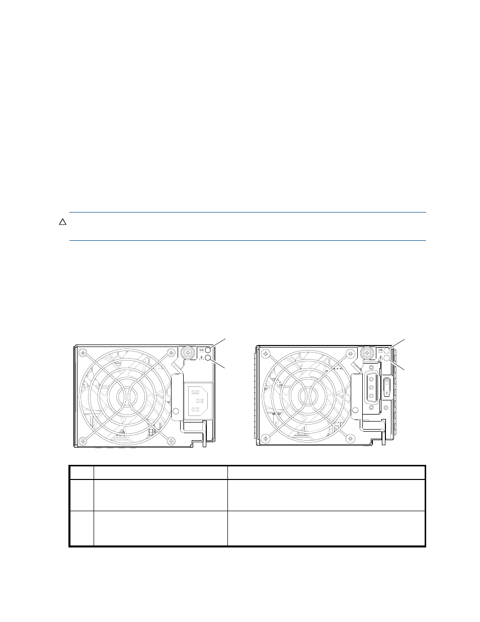
Figure 38 LEDs: MSA 2040 Storage system enclosure power supply modules
AC model
DC model
LED
Description
Definition
1
Input Source Power Good
Green — Power is on and input voltage is normal.
Off — Power is off or input voltage is below the minimum
threshold.
2
Voltage/Fan Fault/Service Required
Amber — Output voltage is out of range or a fan is operating
below the minimum required RPM.
Off — Output voltage is normal.
1
2
1
2