HP MSA 2040 SAN Storage User Manual
Page 26
26
Installing the enclosures
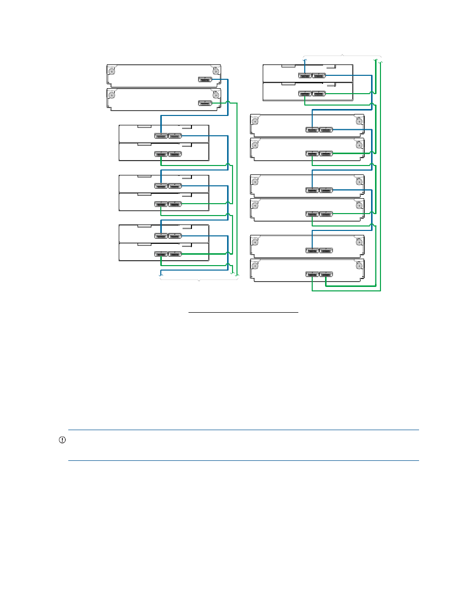
Figure 15 Cabling connections showing maximum enclosures of mixed model type
The illustration above shows a sample maximum enclosures configuration. The diagram shows mixed
model drive enclosures within the dual-controller array using fault-tolerant cabling. In this example, the LFF
drive enclosures follow the SFF drive enclosures. Given that both drive enclosure models use 6 Gb SAS
link-rate and SAS2.0 expanders, they can be ordered in desired sequence within the array, following the
controller enclosure. MSA 2040 controller enclosures support up to eight enclosures (including the
controller enclosure) for adding storage.
IMPORTANT:
For comprehensive configuration options and associated illustrations, refer to the HP MSA
2040 Cable Configuration Guide.
1B
1A
Controller A
Controller B
2B
2A
3B
3A
4B
4A
5B
5A
6B
6A
7B
7A
8B
8A
Continued above right
(see enclosure 5)
Continued from below left
(see enclosure 4)
P1
P1
P2
P2
1
P1
P1
P2
P2
1
P1
P1
P2
1
P1
P1
P2
P2
1
Out
In
Out
In
2
Out
In
Out
In
2
Out
In
Out
In
2
= SFF 25-drive enclosure
1
= LFF 12-drive enclosure
2
Drive enclosure IOM face plate key:
P2
- StorageWorks MSL6000 Tape Library (61 pages)
- Лент-е накопители HP StoreEver DAT (64 pages)
- Лент-е накопители HP StoreEver DAT (50 pages)
- Linear Tape File System Software (25 pages)
- StoreEver Ultrium Tape Drives (78 pages)
- StoreEver Ultrium Tape Drives (76 pages)
- Linear Tape File System Software (20 pages)
- StoreEver Ultrium Tape Drives (61 pages)
- StoreEver TapeAssure Software (40 pages)
- StoreEver Ultrium Tape Drives (75 pages)
- StoreEver Ultrium Tape Drives (60 pages)
- Linear Tape File System Software (28 pages)
- 2600fx Optical Disk Drive (65 pages)
- Ленточный автозагрузчик HP StorageWorks DAT 72x10 (58 pages)
- StorageWorks 1000 Modular Smart Array (72 pages)
- StorageWorks 1000 Modular Smart Array (81 pages)
- StorageWorks 1500cs Modular Smart Array (48 pages)
- StorageWorks 1500cs Modular Smart Array (52 pages)
- StorageWorks 1500cs Modular Smart Array (71 pages)
- 2000fc Modular Smart Array (150 pages)
- Servidor de almacenamiento HP ProLiant DL585 G2 (152 pages)
- Sistemas de almacenamiento de red HP StorageWorks X3000 (152 pages)
- Software de HP StoreVirtual VSA (127 pages)
- Software de HP StoreVirtual VSA (85 pages)
- X500 Data Vault (331 pages)
- StorageWorks 1000i Virtual Library System (122 pages)
- XP Array Manager Software (101 pages)
- StorageWorks XP Remote Web Console Software (20 pages)
- 200 Storage Virtualization System (176 pages)
- StorageWorks MSA 2.8 SAN Switch (22 pages)
- StorageWorks MSA 2.8 SAN Switch (104 pages)
- StorageWorks MSA 2.8 SAN Switch (270 pages)
- StorageWorks MSA 2.8 SAN Switch (307 pages)
- StorageWorks All-in-One SB600c Storage Blade (80 pages)
- StorageWorks All-in-One SB600c Storage Blade (78 pages)
- StorageWorks All-in-One SB600c Storage Blade (60 pages)
- StorageWorks All-in-One SB600c Storage Blade (72 pages)
- ProLiant DL585 G2 Storage-Server (150 pages)
- Data Protector Express Basic-Software (83 pages)
- Data Protector Express Basic-Software (93 pages)
- ProLiant High Availability Storage Server (72 pages)
- ProLiant DL185 G5 Storage Server (174 pages)
- P2000 G3 MSA Array Systems (58 pages)
- StorageWorks 2000fc G2 Modular Smart Array (76 pages)
- 2000I G2-Modular-Smart-Array (48 pages)