HP MSA 2040 SAN Storage User Manual
Page 25
Connecting controller and drive enclosures
25
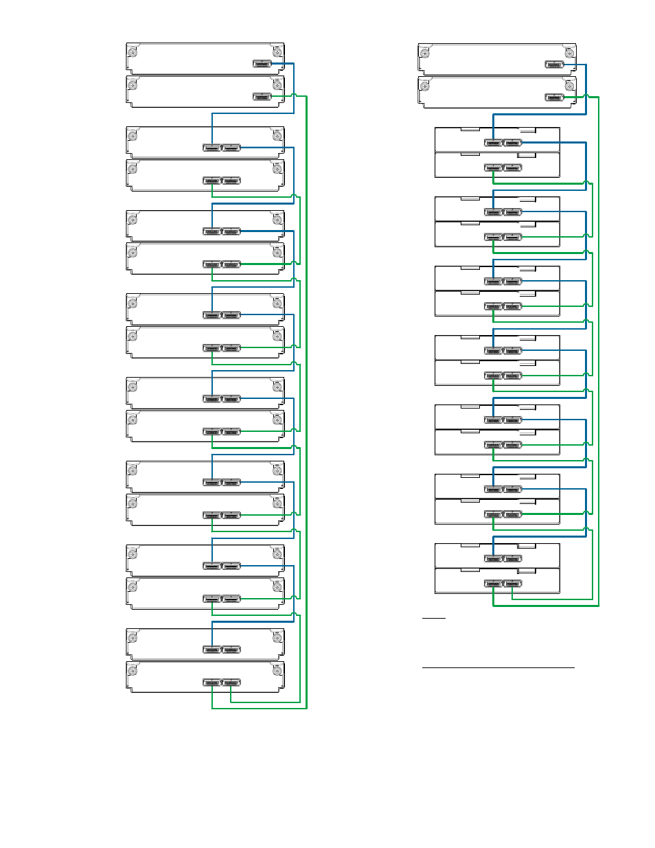
Figure 14 Fault-tolerant cabling connections showing maximum number of enclosures of same type
The figure above provides sample diagrams reflecting fault-tolerant cabling of a maximum number of
supported MSA 2040 enclosures. The diagram at left shows fault-tolerant cabling of an MSA 2040
controller enclosure and seven LFF drive enclosures; whereas the diagram at right shows fault-tolerant
cabling of an MSA 2040 controller enclosure and seven D2700 drive enclosures.
P1
Controller A
Controller B
1A
1B
P2
P1
P1
P1
P1
P1
2A
2B
3A
3B
4A
4B
P2
P2
P2
P2
P2
= LFF 12-drive enclosure
1
= SFF 25-drive enclosure
2
Drive enclosure IOM face plate key:
Controller A
Controller B
In
Out
In
Out
In
Out
In
Out
In
Out
1A
1B
2A
2B
3A
3B
4A
4B
8A
8B
In
Out
In
Out
5A
5B
In
Out
In
Out
6A
6B
In
Out
In
Out
7A
7B
In
Out
In
Out
Note:
The maximum number of supported drive
enclosures (7) may require purchase of
additional longer cable.
2
2
2
1
1
1
1
1
1
1
P2
P1
P2
P1
8A
8B
P1
P1
5A
5B
P2
P2
2
P1
P1
6A
6B
P2
P2
2
P1
P1
7A
7B
P2
P2
2
2
In
Out
- StorageWorks MSL6000 Tape Library (61 pages)
- Лент-е накопители HP StoreEver DAT (64 pages)
- Лент-е накопители HP StoreEver DAT (50 pages)
- StoreEver Ultrium Tape Drives (78 pages)
- StoreEver Ultrium Tape Drives (76 pages)
- Linear Tape File System Software (20 pages)
- StoreEver Ultrium Tape Drives (61 pages)
- StoreEver TapeAssure Software (40 pages)
- StoreEver Ultrium Tape Drives (75 pages)
- StoreEver Ultrium Tape Drives (60 pages)
- Linear Tape File System Software (28 pages)
- Linear Tape File System Software (25 pages)
- 2600fx Optical Disk Drive (65 pages)
- Ленточный автозагрузчик HP StorageWorks DAT 72x10 (58 pages)
- StorageWorks 1000 Modular Smart Array (81 pages)
- StorageWorks 1500cs Modular Smart Array (48 pages)
- StorageWorks 1500cs Modular Smart Array (52 pages)
- StorageWorks 1500cs Modular Smart Array (71 pages)
- 2000fc Modular Smart Array (150 pages)
- StorageWorks 1000 Modular Smart Array (72 pages)
- Servidor de almacenamiento HP ProLiant DL585 G2 (152 pages)
- Sistemas de almacenamiento de red HP StorageWorks X3000 (152 pages)
- Software de HP StoreVirtual VSA (127 pages)
- Software de HP StoreVirtual VSA (85 pages)
- X500 Data Vault (331 pages)
- StorageWorks 1000i Virtual Library System (122 pages)
- StorageWorks XP Remote Web Console Software (20 pages)
- 200 Storage Virtualization System (176 pages)
- XP Array Manager Software (101 pages)
- StorageWorks MSA 2.8 SAN Switch (22 pages)
- StorageWorks MSA 2.8 SAN Switch (104 pages)
- StorageWorks MSA 2.8 SAN Switch (270 pages)
- StorageWorks MSA 2.8 SAN Switch (307 pages)
- StorageWorks All-in-One SB600c Storage Blade (60 pages)
- StorageWorks All-in-One SB600c Storage Blade (72 pages)
- StorageWorks All-in-One SB600c Storage Blade (80 pages)
- StorageWorks All-in-One SB600c Storage Blade (78 pages)
- ProLiant DL585 G2 Storage-Server (150 pages)
- Data Protector Express Basic-Software (83 pages)
- Data Protector Express Basic-Software (93 pages)
- ProLiant DL185 G5 Storage Server (174 pages)
- ProLiant High Availability Storage Server (72 pages)
- StorageWorks 2000fc G2 Modular Smart Array (76 pages)
- 2000I G2-Modular-Smart-Array (48 pages)
- P2000 G3 MSA Array Systems (58 pages)