Figure 11 – HP MSA 2040 SAN Storage User Manual
Page 22
22
Installing the enclosures
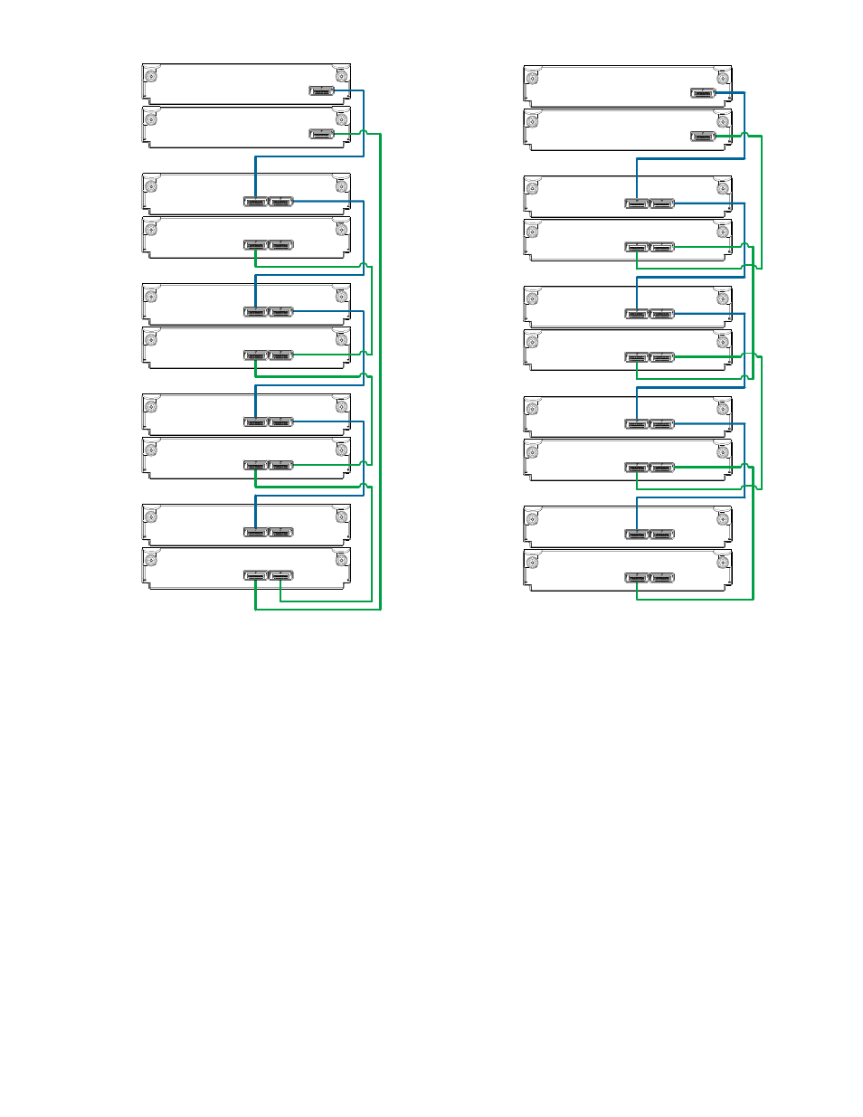
Figure 11 Cabling connections between MSA 2040 controllers and LFF drive enclosures
The diagram at left (above) shows fault-tolerant cabling of a dual-controller enclosure cabled to MSA 2040
6 Gb 3.5" 12-drive enclosures featuring dual-expansion modules. Controller module 1A is connected to
expansion module 2A, with a chain of connections cascading down (blue). Controller module 1B is
connected to the lower expansion module (5B), of the last drive enclosure, with connections moving in the
opposite direction (green). Fault-tolerant cabling allows any drive enclosure to fail—or be removed—while
maintaining access to other enclosures.
The diagram at right (above) shows the same storage components connected using straight-through
cabling. Using this method, if a drive enclosures fails, the enclosures that follow the failed enclosure in the
chain are no longer accessible until the failed enclosure is repaired or replaced.
Controller A
Controller B
1A
1B
In
Out
2A
2B
3A
3B
4A
4B
5A
5B
In
Out
In
Out
In
Out
In
Out
In
Out
In
Out
Out
In
Fault-tolerant cabling
Controller A
Controller B
1A
1B
In
Out
2A
2B
3A
3B
4A
4B
5A
5B
In
Out
In
Out
In
Out
In
Out
In
Out
In
Out
Out
In
Straight-through cabling
- StorageWorks MSL6000 Tape Library (61 pages)
- Лент-е накопители HP StoreEver DAT (64 pages)
- Лент-е накопители HP StoreEver DAT (50 pages)
- StoreEver Ultrium Tape Drives (61 pages)
- StoreEver TapeAssure Software (40 pages)
- StoreEver Ultrium Tape Drives (75 pages)
- StoreEver Ultrium Tape Drives (60 pages)
- Linear Tape File System Software (28 pages)
- Linear Tape File System Software (25 pages)
- StoreEver Ultrium Tape Drives (78 pages)
- StoreEver Ultrium Tape Drives (76 pages)
- Linear Tape File System Software (20 pages)
- 2600fx Optical Disk Drive (65 pages)
- Ленточный автозагрузчик HP StorageWorks DAT 72x10 (58 pages)
- StorageWorks 1500cs Modular Smart Array (52 pages)
- StorageWorks 1500cs Modular Smart Array (71 pages)
- 2000fc Modular Smart Array (150 pages)
- StorageWorks 1000 Modular Smart Array (72 pages)
- StorageWorks 1000 Modular Smart Array (81 pages)
- StorageWorks 1500cs Modular Smart Array (48 pages)
- Servidor de almacenamiento HP ProLiant DL585 G2 (152 pages)
- Sistemas de almacenamiento de red HP StorageWorks X3000 (152 pages)
- Software de HP StoreVirtual VSA (127 pages)
- Software de HP StoreVirtual VSA (85 pages)
- X500 Data Vault (331 pages)
- StorageWorks 1000i Virtual Library System (122 pages)
- StorageWorks XP Remote Web Console Software (20 pages)
- 200 Storage Virtualization System (176 pages)
- XP Array Manager Software (101 pages)
- StorageWorks MSA 2.8 SAN Switch (307 pages)
- StorageWorks MSA 2.8 SAN Switch (22 pages)
- StorageWorks MSA 2.8 SAN Switch (104 pages)
- StorageWorks MSA 2.8 SAN Switch (270 pages)
- StorageWorks All-in-One SB600c Storage Blade (72 pages)
- StorageWorks All-in-One SB600c Storage Blade (80 pages)
- StorageWorks All-in-One SB600c Storage Blade (78 pages)
- StorageWorks All-in-One SB600c Storage Blade (60 pages)
- ProLiant DL585 G2 Storage-Server (150 pages)
- Data Protector Express Basic-Software (83 pages)
- Data Protector Express Basic-Software (93 pages)
- ProLiant DL185 G5 Storage Server (174 pages)
- ProLiant High Availability Storage Server (72 pages)
- 2000I G2-Modular-Smart-Array (48 pages)
- P2000 G3 MSA Array Systems (58 pages)
- StorageWorks 2000fc G2 Modular Smart Array (76 pages)