Disk drives used in msa 2040 enclosures, Controller enclosure-rear panel layout, Controller enclosure—rear panel layout – HP MSA 2040 SAN Storage User Manual
Page 14: 3 msa 2040 array: rear panel
14
Components
Disk drives used in MSA 2040 enclosures
MSA 2040 enclosures support LFF/SFF Midline SAS, LFF/SFF Enterprise SAS, and SFF SSD disks. For
information about creating vdisks and adding spares using these different disk drive types, see the
HP MSA 2040 SMU Reference Guide and HP MSA 2040 Solid State Drive Read This First document.
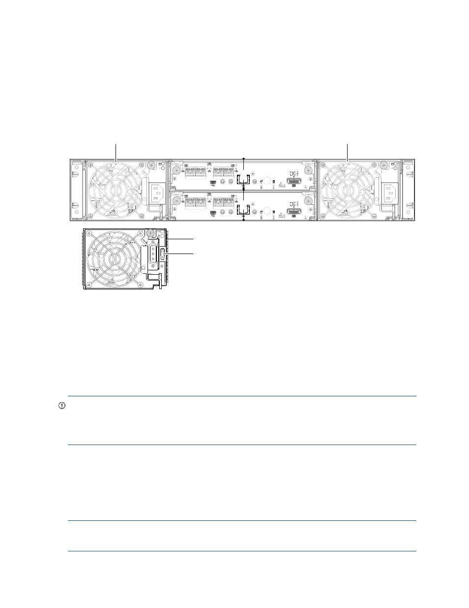
Controller enclosure—rear panel layout
The diagram and table below display and identify important component items comprising the rear panel
layout of the MSA 2040 controller enclosure (MSA 2040 SAN is shown in the example).
Figure 3 MSA 2040 Array: rear panel
A controller enclosure accommodates two power supply FRUs of the same type—either both AC or both
DC—within the two power supply slots (see two instances of callout 1 above). The controller enclosure
accommodates two controller module FRUs of the same type within the I/O module slots (see callouts 2
and 3 above).
IMPORTANT:
If the MSA 2040 controller enclosure is configured with a single controller module, the
controller module must be installed in the upper slot (see callout 2 above), and an I/O module blank must
be installed in the lower slot (see callout 3 above). This configuration is required to allow sufficient air flow
through the enclosure during operation.
The diagrams with tables that immediately follow provide descriptions of the different controller modules
and power supply modules that can be installed into the rear panel of an MSA 2040 controller enclosure.
Showing controller modules and power supply modules separately from the enclosure provides improved
clarity in identifying the component items called out in the diagrams and described in the tables.
Descriptions are also provided for optional drive enclosures supported by MSA 2040 controller enclosures
for expanding storage capacity.
NOTE:
MSA 2040 controller enclosures support hot-plug replacement of redundant controller modules,
fans, power supplies, and I/O modules. Hot-add of drive enclosures is also supported.
1
AC Power supplies
2
Controller module A (see face plate detail figures)
3
Controller module B (see face plate detail figures)
4
DC Power supply (2) — (DC model only)
5
DC Power switch
CACHE
LINK
ACT
6Gb/s
CACHE
LINK
ACT
6Gb/s
CLI
CLI
PORT 3
PORT 4
SERVICE−1
SERVICE−2
PORT 1
PORT 2
CLI
CLI
PORT 3
PORT 4
SERVICE−1
SERVICE−2
PORT 1
PORT 2
1
1
5
4
2
3
MSA 2040 controller enclosure
(rear panel locator illustration)