Sterlco SSL and SSIL Series Hopper Loaders User Manual
Page 16
16
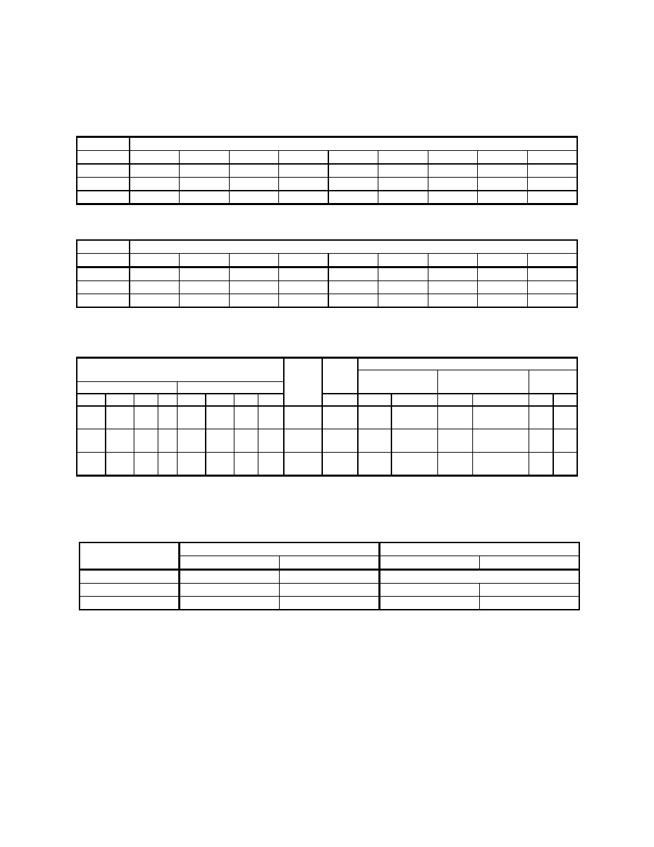
Figure 5:
SSIL Series Dimensions, Specifications, and Maximum Machine-Side Throughput
American Standards
Capacity Dimensions
in
inches
cu. ft.
A
B
C
D
E -sq.
G -sq.
H -sq.
I -sq. c J
0.1
27
5
/
8
”
17” 6
3
/
8
”
1
3
/
4
” 4” 2” 1
1
/
4
” 2
1
/
2
” 2”
0.2 35
1
/
4
” 19
1
/
2
” 9
1
/
8
”
3”
7”
3
1
/
2
” 2
3
/
4
” 5
1
/
2
” 3”
0.4 41
1
/
4
” 25
3
/
4
” 9
1
/
8
”
3”
7”
3
1
/
2
” 2
3
/
4
” 5
1
/
2
” 3”
Metric Standards
Capacity Dimensions
in
cm
liters
A
B
C
D
E -sq.
G -sq.
H -sq.
I -sq. c J
2.8 74.0 41.9 16.2 4.4 10.2 5.1 3.2 6.3 5.1
5.6 89.5 49.5 23.2 7.6 17.8 8.9 7.0 14.0 7.6
11.3 104.8 65.4 23.2 7.6 17.8 8.9 7.0 14.0 7.6
c
0.281” (7.1 mm) -diameter holes; four (4) places equally spaced.
SSIL/CSIL Series Specifications
Full-
Specifications
Selection
load Inlet/outlet
Square mounting Shipping
Hopper capacity
Sight glass capacity Model amps
range flange
dimensions
weight
cu. ft. liters lbs. Kg cu. ft. liters lbs. Kg
no. FLA
inches
mm
inches
mm
lbs. Kg
0.1
2.8 3.5 1.5 0.02 0.57 0.68 0.31
SSIL/
CSIL03
11 1½”
38 mm
4”
101.6
50 23
0.2
5.6 7.0 3.1 0.09 2.55 3.25 1.48
SSIL/
CSIL06
11 1½”
38 mm
7”
177.8
70 32
0.4 11.3 14.0 6.3 0.09 2.55 3.25 1.48
SSIL/
CSIL11
11 1½”
38 mm
7”
177.8
72 33
SSIL/CSIL Series Maximum Machine-Side Throughput
Twelve (12) -foot (3.66 m) vertical 1½” OD (approx. 38 mm) flex hose; pellets @ 35 lbs./cu. ft. (560 Kg/cu. m)
Model Non-Proportioning
c
Proportioning
number lbs./hr. Kg/hr. lbs./hr. Kg/hr.
SSIL/CSIL03 150
68
Not available
SSIL/CSIL06 500
227
400
182
SSIL/CSIL11 1,000
454
800
364
c
Maximum throughput beside-the-press loading; includes 12-foot (3.6 m) vertical lift.
We are committed to a continuing program of product improvement.
Specifications, appearances, and dimensions are subject to change without notice.