Setra System SRPM User Manual
Page 12
12
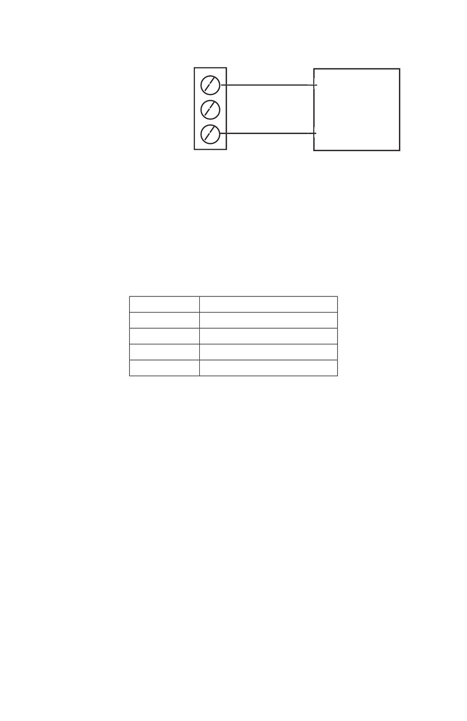
1. V Out: 0 to 5, 0 to 10 VDC
2. C Out: 4 to 20 mA
3. Common
●
●
●
●
●
●
●
●
Receiver
(V)
+
–
Voltage Output
3.3.5 BACnet
BACnet hardware is implemented as isolated RS485. Wire to Connector
J2, labeled RS-485. Connect tx line to +(A), rx to –(B) and ground wires
to S. Connect Shields together with wire nut.
Hardware confi guration is done using a 5 position dip switch (S1) located
in the upper right hand section of the PCBA as well as through the touch
screen interface, see Section 4.4. and 4.9.
Position
Function
1
MAC address enable
2
N/C Not Connected
3
Pull Up Resistor
4
Termination Resistor
5
Pull Down Resistor
Use a small fl at blade screwdriver or pen to push the switch to the right
to turn that function on, otherwise it is off.
There is a BACnet setup screen that is enabled by pushing position 1
switch to the “on” position. After confi guration the switch must be moved
to the “off” position.
- Model ASM (8 pages)
- Model 204 (4 pages)
- Model 209 (4 pages)
- Model 227 (8 pages)
- 264 (4 pages)
- 269 (4 pages)
- Model 280E (4 pages)
- Model 370 (48 pages)
- Model 526 (7 pages)
- Model 540 (9 pages)
- Model 595 (8 pages)
- Model 869 (28 pages)
- Model 321 (4 pages)
- Model SRH (12 pages)
- Model Datum 2000 (31 pages)
- Model 217 (8 pages)
- Model 230 (12 pages)
- Model 242901-06 (1 page)
- Model 265 (4 pages)
- Model 270 (5 pages)
- Model 299 (4 pages)
- Model 470 (35 pages)
- Model 524 (6 pages)
- Model 546 (8 pages)
- Model 730 (16 pages)
- GCT-225 (8 pages)
- Model 141 (4 pages)
- Model 205-2 (4 pages)
- Model 223 (8 pages)
- Model 231 (12 pages)
- Model 256 (8 pages)
- Model 276 (2 pages)
- Model 3100 (8 pages)
- Model 516 (6 pages)
- Model 550 (9 pages)
- Model 760 (18 pages)
- Model LD330 (4 pages)
- Model SRMD (8 pages)
- Model 201 (4 pages)
- Setra Model 206 (4 pages)
- Model 224 (8 pages)
- Model 231RS (16 pages)
- 260 (2 pages)
- 267MR (14 pages)
- Model 278 (2 pages)