Setra System SRPM User Manual
Page 11
11
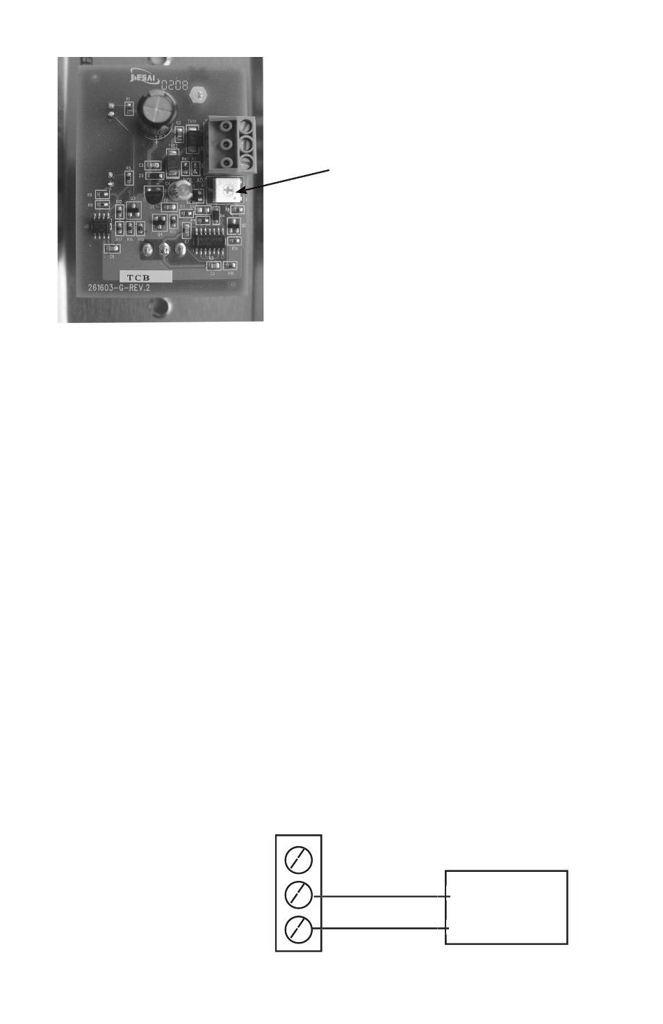
The volume control on the Annunciator is a potentiometer that can be
adjusted from 0 to 85 dB. Using a small fl at bladed screwdriver, rotate
potentiometer (remote annunciator PC board) clockwise to increase
volume and counterclockwise to decrease volume.
3.3.3 DOOR STATUS SWITCH WIRING
Install the door switch into the door jamb. Wire to the normally open
(N.O.) side of the door jamb contact switch. The SRPM will indicate
the status of door position. A contact closure indicates that the door is
closed. This is a low voltage circuit (5 VDC). Run 2 wires from the door
switch to connector J6 on the SRPM (See Section 8.0). The door input
status function is enabled in the SETUP ALARMS menu screen, section
4.7
3.3.4 ANALOG OUTPUT
The SRPM can be confi gured to have either current (4 to 20 mA) or
voltage (0 to 5 or 0 to 10 VDC) outputs. Voltage output--pin 1, Current
output--pin 2, Common--pin 3. Note: No external excitation is required.
.
Current Output
The SRPM supplies it’s own loop power, do not wire in a separate power
supply.
Audible Alarm
Potentiometer
1. V Out: 0 to 5, 0 to 10 VDC
2. C Out: 4 to 20 mA
3. Common
●
●
●
●
●
●
●
●
Receiver
(mA)
+
–