Analog output connections, 7 analog output connections – ROTRONIC MBW 473 User Manual
Page 29
MBW473_MANUAL_E_V2.0
25
4.7 Analog Output Connections
The 473 can be ordered with two optional analog outputs which are independently configurable.
If the instrument is ordered with the optional analog outputs, a 4-pin LEMO connector will be supplied
with the instrument, which can be used to fabricate a custom cable for your application.
The 473 requires a 4-pin LEMO connector (www.lemo.ch).
Part Number: FGG 1B 304 CLAD 42.
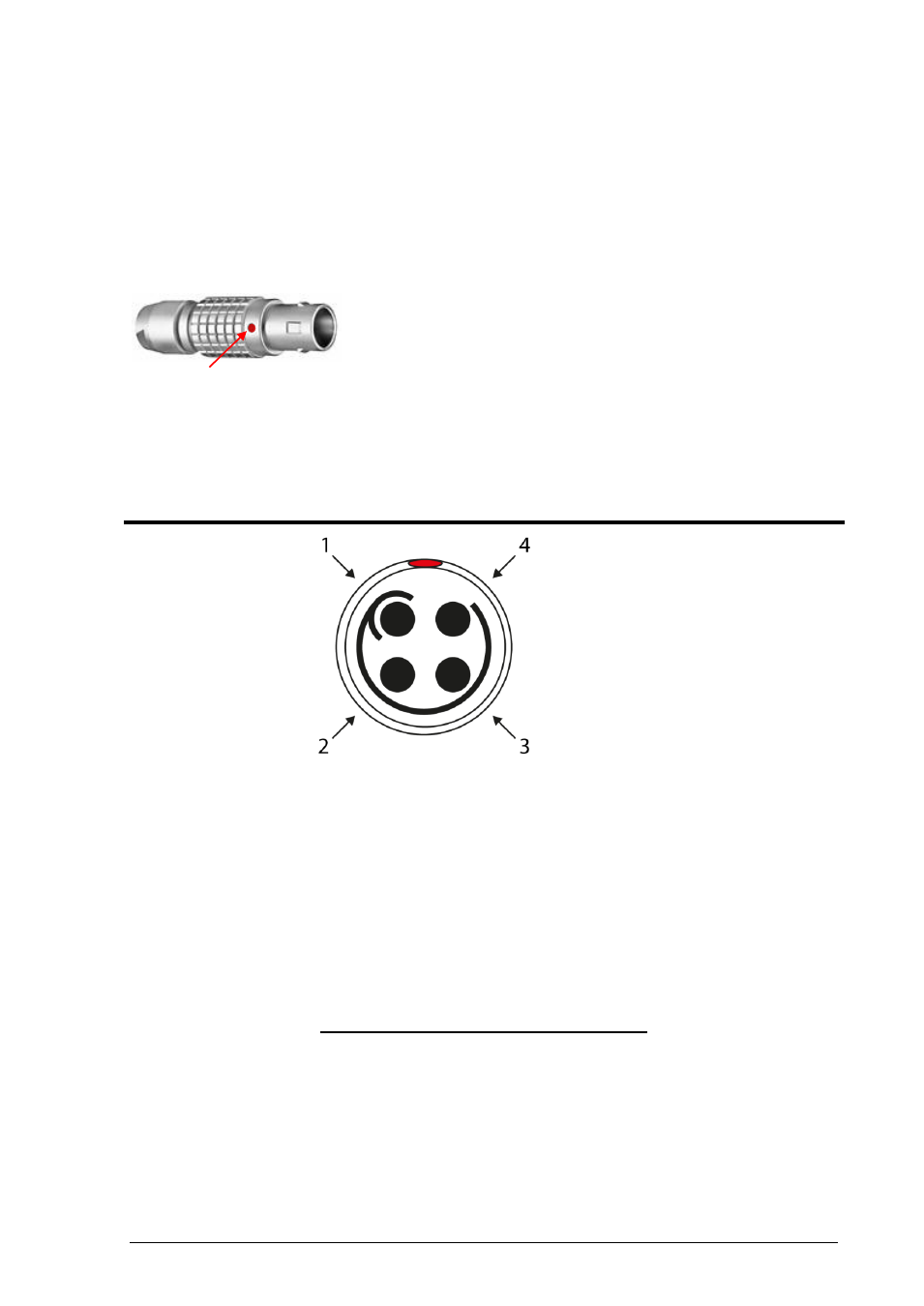
When the 4-pin LEMO connector is properly assembled, the red dot of the connector housing should
be between pin 1 and 4.
The 473 allows both a voltage and a current output signal. As shown in the illustration above, pins 1 and
2 supply the voltage signal (V), and pins 3 and 4 supply the current signal (I). Inside the instrument, the
output signal is connected to a D/A converter and then split into a voltage and a current signal. Therefore
you may use either a volt or current meter to receive the analog signal. The maximum voltage output
range is -
10…+10 V. See the following table to identify the corresponding current signal.
Voltage
[V]
Current
[mA]
+10
20
2
4
0
0
-10
N/A
Pin
Signal
Position
Description
1
+V
When viewing the solder tubs of a
disassembled 4-pin LEMO connector,
pin 1 is usually identified with a full or
partial circle drawn around it. Pin 4
should have no identifier. When wiring
the cable, note that the pin numbering
of the socket in the back panel of the
instrument starts at the top left (pin 1)
and
goes
counter-clockwise
(as
viewed from the rear of the unit).
2
-V
3
+I
4
-I
The red dot is between pin 1 and 4.