3 interface, Interface, Table 3-1: sentral m&m module pin assignments – PNI SENtral MandM User Manual
Page 9: 3interface
PNI Sensor Corporation
Doc #1020129 revE
SENtral M&M Technical Datasheet
Page 8
3
Interface
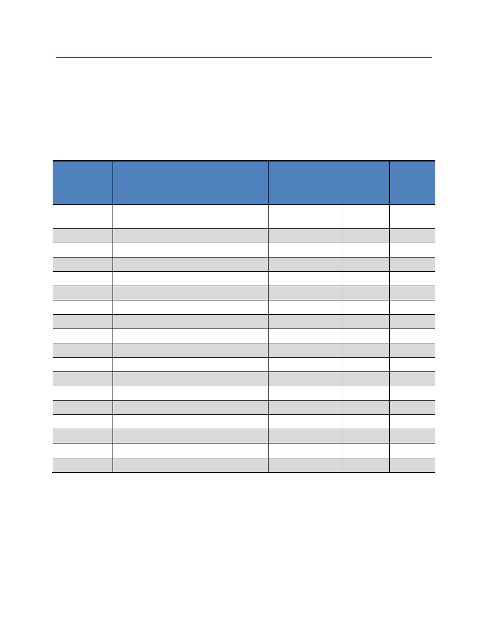
The SENtral M&M pin-out is given in Table 3-1. Pin-outs also are given alongside the device
mechanical drawings in Section 5. See Table 2-3 for the operating ranges of DVDD, DVDD2,
and AVDD. A discussion of the communication interface follows the table.
Table 3-1: SENtral M&M Module Pin Assignments
Pin Name
Description
M&M Orange,
Red, Green, &
Yellow Pin#
M&M
White
Pin #
M&M
Blue
Pin #
DVDD
Digital Supply Voltage
– Sensors &
EEPROM
1
NA
2
DVDD2
Supply Voltage
– SENtral
2
D1
2
AVDD
Analog Supply Voltage
– Sensors
7
NA
7
GND
Ground
8
D2
8
SCLS
I
2
C host bus SCL clock line
3
B1
3
SDAS
I
2
C host bus SDA data line
5
A1
5
SDAM
I
2
C sensor bus SDA data line
9
A4
9
SCLM
I
2
C sensor bus SCL clock line
10
B4
10
GPIO[0]
SENtral Accelerometer Interrupt
--
D4
--
GPIO[1]
SENtral Magnetometer Interrupt
--
C4
--
GPIO[2]
SENtral Gyroscope Interrupt
--
A3
--
GPIO[3]
Reserved
--
B3
--
GPIO[4]
Reserved
6
A2
6
GPIO[5]
Reserved
--
B2
--
GPIO[6]
Host Event Interrupt
4
C1
4
SA0
Slave Address Pin 0
--
C3
--
VCAP
Regulator Capacitor
--
D3
--
Reserved
Reserved (not connected)
--
C2
1, 12, 13
Communication with the host processor is via SENtral’s I
2
C host interface, where the SENtral
M&M acts as a slave device and the host’s processor acts as the master. The host interrupt line
informs the host system when SENtral has updated measurement data. The SENtral Motion
Coprocessor on the SENtral M&M module communicates with the module’s sensors over the
sensor bus, where SENtral is the I
2
C master and the sensors are slave devices.