2 i2c host interface (host bus), C host interface (host bus), Table 3-2: i – PNI SENtral MandM User Manual
Page 11: C timing parameters
PNI Sensor Corporation
Doc #1020129 revE
SENtral M&M Technical Datasheet
Page 10
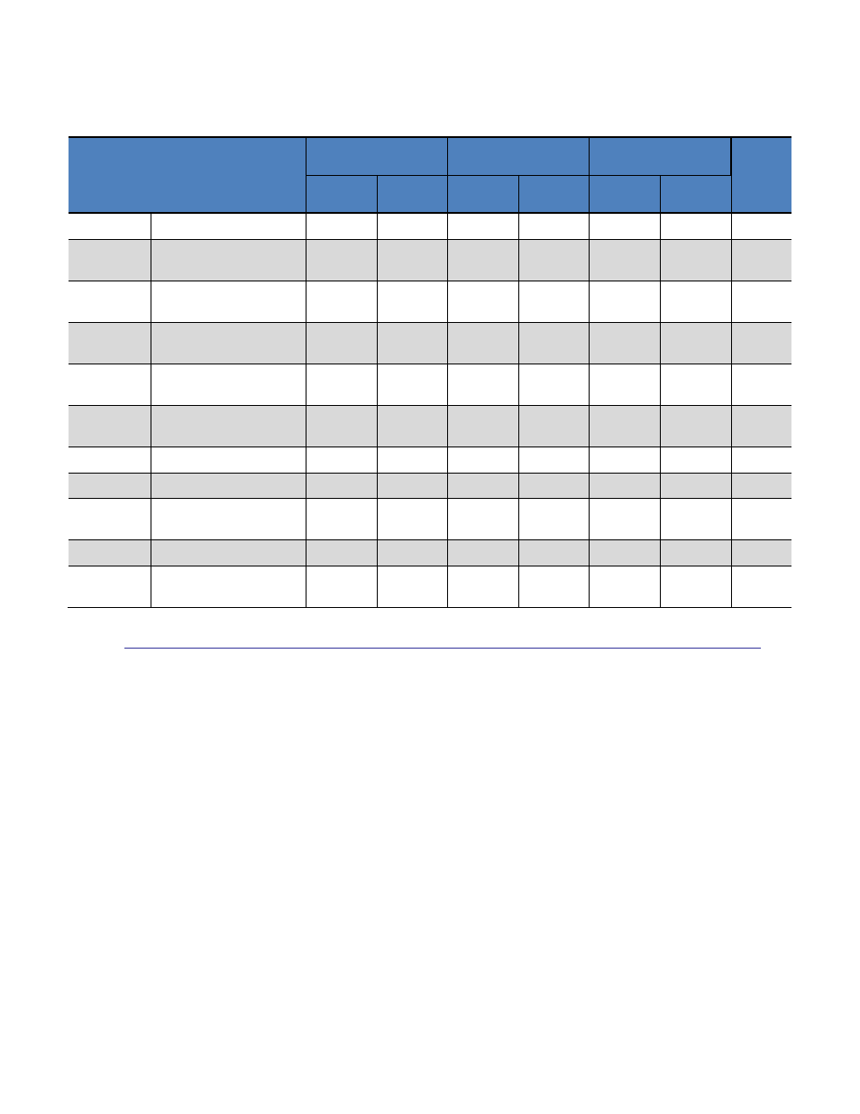
Table 3-2: I
2
C Timing Parameters
Standard
Fast
Fast Plus
Units
Symbol
Parameter
Min
Max
Min
Max
Min
Max
f
SCL
SCL Clock
0
100
0
400
0
1000
kHz
t
r
SDA & SCL Rise
Time
-
1000
20
300
120
ns
t
f
SDA & SCL Fall Time
-
300
20*(V
DD
/
5.5V)
300
20*(V
DD
/
5.5V)
120
ns
t
LOW
LOW period of SCL
Clock
4.7
-
1.3
-
0.5
-
s
t
HIGH
HIGH period of SCL
Clock
4.0
-
0.6
-
0.26
-
s
t
HD;STA
Hold time (repeated)
START
4.0
-
0.6
-
0.26
-
s
t
HD;DAT
Data hold time
0
-
0
-
0
-
s
t
SU:DAT
Data set-up time
250
-
100
-
50
-
ns
t
SU;STA
Set-Up time for
repeated Start
4.7
-
0.6
-
0.26
-
s
t
SU;STO
Stop set-up time
4.0
-
0.6
-
0.26
-
s
t
BUF
Bus free time between
STOP & START
4.7
-
1.3
-
0.5
-
s
3.2 I
2
C Host Interface (Host Bus)
The host will control the SENtral M&M on the host bus via SENtral’s I
2
C host interface.
The host interface consists of 2 wires: the serial clock, SCLS, and the serial data line, SDAS.
Both lines are bi-directional. SENtral is connected to the host bus via the SDAS and SCLS
pins, which incorporate open drain drivers within the device. Note the SENtral M&M
module incorporates 4.7 kΩ pull-up resistors on the host bus clock and data lines, so if the
host system also incorporates pull-up resistors on these line the resistors will act in parallel.
The SENtral M&M’s 7-bit I
2
C slave address is 0x28 (0b0101000). The shifted address is
0x50.
Data transfer is always initiated by the host. Data is transferred between the host and
SENtral serially through the data line, SDAS, in an 8-bit transfer format. The transfer is
synchronized by the serial clock line, SCLS. Supported transfer formats are single-byte read,
multiple-byte read, single-byte write, and multiple-byte write. The data line can be driven