4 standby state, Standby state, Table 4-4: results registers – PNI SENtral MandM User Manual
Page 20: On), 4.4
PNI Sensor Corporation
Doc #1020129 revE
SENtral M&M Technical Datasheet
Page 19
matrix, or Euler angles (heading, pitch, and roll), see Appendix I. The resolution is
32 kHz for all timestamps.
Note: All multi-byte elements are stored and transmitted using the Little Endian convention: the
least significant byte is stored at the lowest address and transmitted first over the I
2
C bus.
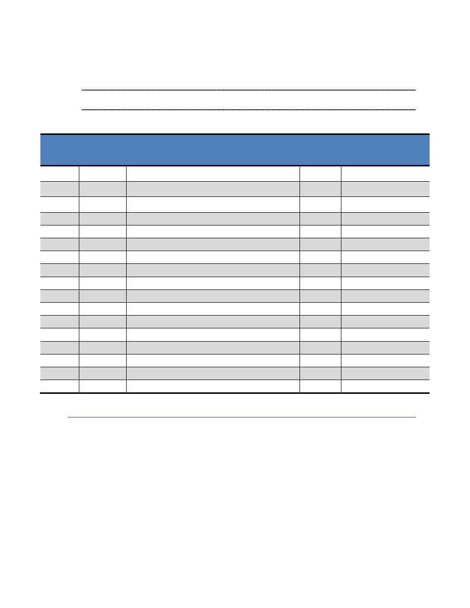
Table 4-4: Results Registers
Name
Address
(Hex)
Description
Format
Full-Scale Range
QX
00
– 03
Normalized Quaternion
– X, or Heading
Float32
0.0
– 1.0, or ±
QY
04
– 07
Normalized Quaternion
– Y, or Pitch
Float32
0.0
– 1.0, or ±
/2
QZ
08
– 0B
Normalized Quaternion
– Z, or Roll
Float32
0.0
– 1.0, or ±
QW
0C
– 0F
Normalized Quaternion
– W, or 0.0
Float32
0.0
– 1.0
QTime
10
– 11
Quaternion Data Timestamp
UInt16
0
– 2048 msec
MX
12
– 13
Magnetic Field
– X Axis, or Raw Mag Data
Int16
±1000 µT when scaled
MY
14
– 15
Magnetic Field
– Y Axis, or Raw Mag Data
Int16
±1000 µT when scaled
MZ
16
– 17
Magnetic Field
– Z Axis, or Raw Mag Data
Int16
±1000 µT when scaled
MTime
18
– 19
Magnetometer Interrupt Timestamp
UInt16
0
– 2048 msec
AX
1A
– 1B
Linear Acceleration
– X Axis, or Raw Accel Data
Int16
±16 g when scaled
AY
1C
– 1D
Linear Acceleration
– Y Axis, or Raw Accel Data
Int16
±16 g when scaled
AZ
1E
– 1F
Linear Acceleration
– Z Axis, or Raw Accel Data
Int16
±16 g when scaled
ATime
20
– 21
Accelerometer Interrupt Timestamp
UInt16
0
– 2048 msec
GX
22
– 23
Rotational Velocity
– X Axis, or Raw Gyro Data
Int16
±5000°/s when scaled
GY
24
– 25
Rotational Velocity
– Y Axis, or Raw Gyro Data
Int16
±5000°/s when scaled
GZ
26
– 27
Rotational Velocity
– Z Axis, or Raw Gyro Data
Int16
±5000°/s when scaled
GTime
28
– 29
Gyroscope Interrupt Timestamp
UInt16
0.0
– 2.048 sec
4.4 Standby State
In Standby State overall system power consumption is dramatically reduced because both the
SENtral algorithm and the sensors are shut down. Table 4-5 provides the registers associated
with Standby State.