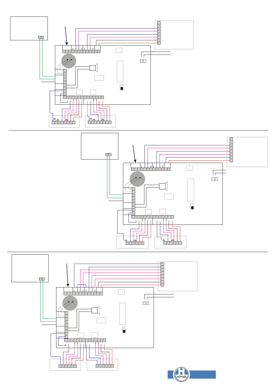
Configuration for a conventional 4 wire system, Configuration for eol with tamper and anti-mask, Device 2 eg pir, viper door contact – Hoyles Zoneguard Grade 3 Zone Omit EN50131-3:2009 Env. Class II User Manual
Page 4: Control panel control panel control panel
A
B
A
B
A
B
Z1
Z1
Z1
Y1
Y1
Y1
X1
X1
X1
X2
X2
X2
T1
T1
A1
A1
A1
A2
A2
A2
A1
A1
-
-
-
-
-
-
-
-
+
+
+
+
+
+
+
+
+
+
+
+
DETECTION 1
DETECTION 1
DETECTION 1
UNIT
TAMPER
UNIT
TAMPER
UNIT
TAMPER
NC
NC
NC
T2
T2
T2
C2
C2
C2
A2
A2
A2
T1
T1
T1
C1
C1
C1
A1
A1
A1
-
-
-
+
+
+
F +
F +
F +
POWER
POWER
POWER
TO
TO
TO
PANEL
PANEL
PANEL
J1
J1
J1
OPERATIONAL MODE
OPERATIONAL MODE
OPERATIONAL MODE
PROGRAMMING MODE
PROGRAMMING MODE
PROGRAMMING MODE
EOL
Device 2
eg PIR, VIPER
DOOR CONTACT
Device 2
eg PIR, VIPER
DOOR CONTACT
Device 2
eg PIR
Device 1
eg PIR, VIPER
DOOR CONTACT
Device 1
eg PIR, VIPER
DOOR CONTACT
Device 1
eg PIR
ZONE 2
ZONE 2
ZONE 2
ZONE 3
ZONE 3
TAMPER
ZONE 1
ZONE 1
ZONE 1
12v dc
12v dc
12v dc
-
-
-
+
+
+
CONTROL
PANEL
CONTROL
PANEL
CONTROL
PANEL
NOTES
EOL = End of Line Resistor
AMR = Anti Masking Resistor
ALR = Alarm Resistor Min 1k
NOTES
EOL = End of Line resiator
ALR = Alarm Resistor Min 1k
The unit tamper is wired
as Zone 2 tamper
The unit tamper is wired
as Zone 2 tamper
Z2
Z2
Z2
Y2
Y2
Y2
T2
T2
T2
M2
M2
T2
A2
A2
A2
A2
-
-
-
-
DETECTION 2
DETECTION 2
DETECTION 2
-
-
-
+
+
+
SDR
SDR
SDR
RMT 2
RMT 2
RMT 2
R COM
R COM
R COM
RMT 1
RMT 1
RMT 1
KSW
KSW
KSW
TO
TO
TO
PANEL
PANEL
PANEL
NO
NO
NO
C
C
C
A
L
R
A
L
R
A
L
R
A
L
R
EOL
EOL
EOL
AMR
AMR
OMITTED
OMITTED
OMITTED
CONFIGURATION FOR EOL
WITH TAMPER BUT
WITHOUT ANTI-MASK
CONFIGURATION FOR EOL
WITH TAMPER AND ANTI-MASK
CONFIGURATION FOR A
CONVENTIONAL 4 WIRE SYSTEM
These contacts can be taken to a
remote point or data logger to
indicate or record zone omissions.
These contacts can be taken to a
remote point or data logger to
indicate or record zone omissions.
These contacts can be taken to a
remote point or data logger to
indicate or record zone omissions.
Remote device for modes
3 and 4 eg a normally open
remote keyswitch or biometric
reader. In modes 6 and 7 this
would be a device to start the
timer. It is not part of the
alarm monitoring
Remote device for modes
3 and 4 eg a normally open
remote keyswitch or biometric
reader. In modes 6 and 7 this
would be a device to start the
timer. It is not part of the
alarm monitoring
Remote device for modes
3 and 4 eg a normally open
remote keyswitch or biometric
reader. In modes 6 and 7 this
would be a device to start the
timer. It is not part of the
alarm monitoring
-
-
-
+
+
+
OPTIONAL
REMOTE
SOUNDER
OPTIONAL
REMOTE
SOUNDER
OPTIONAL
REMOTE
SOUNDER
Optional remote re-instate.
Apply a momentary +ve
Optional remote re-instate.
Apply a momentary +ve
Optional remote re-instate.
Apply a momentary +ve
Note the unit sounder indicates faults when reinstating. It is NOT a local alarm sounder.
Unused alarmloops on the
detection side must be linked
with a short circuit not a resistor.
The EOL resistor must be
connected as shown and not
connected between alarm and
tamper as conventional.
Unused alarm loops on the
detection side must be linked
with a short circuit.
www.hoyles.com
NOTES
EOL = End of Line resistor ALR =
Alarm Resistor Min 1k
The unit tamper is wired as Zone
2 tamper
Unused alarm loops on the
detection side must be linked with
a short circuit not a resistor.
The EOL resistor must be
connected as shown and not
connected between alarm and
tamper as conventional.
Apply closed circuit from remote
equipment to sound the alarm
tone while the signal is applied
Apply closed circuit from remote equipment to
sound the alarm tone while the signal is applied
Apply closed circuit from remote equipment to
sound the alarm tone while the signal is applied