Mounting method, Acce sso rie s – Hoyles Yellow resettable DPCO call point IP67 User Manual
Page 2
Technical Da
ta for W
aterpr
oof R
eSet Cal
l Point Series 01 & 11
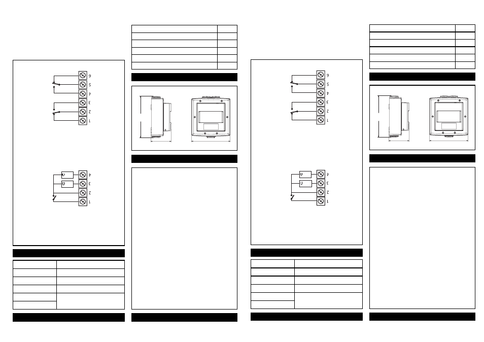
Wat
erproo
f Series 01
Denote
s a Wat
erproo
f ReSe
t Call P
oint that wil
l interf
ace with
most c
onventional fir
e alarm sys
tems. It is fitt
ed with two
internal 1 w
att r
esist
ors 470 and 680 ohm. These are e
asily
acce
ssed thr
ough the installer t
erminals as illustr
ated.
Wat
erproo
f Series 11
Denote
s a Wat
erproo
f ReSe
t Call P
oint that inc
orporat
es tw
o
independent single pole changeover s
witches pr
oviding double
pole changeover c
ontacts. Easily acce
ssed thr
ough installer
terminals as il
lustr
ated.
Curr
ent Rating (Series 01 & 11)
Curr
ent Rating (Series 11 only)
3 Amps 12 - 24V DC
3 Amps 125 - 250V AC
Housing and Mounting Box M
aterial
Poly
carbonate
Electrical Contact M
aterial
Silver pla
ted br
ass
Operating T
emperatur
e
-20°C - +65°C
Instal
lation T
erminal Conduct
or Size
0.5mm - 2.5mm
Wat
erproo
f ReSe
t Series 01 & 11
Specifications
Dimensions
NB:S
witch arr
angements shown with WRP R
eSet in stand
by.
Mounting Method
1.R
emove the W
aterpr
oof R
eSet Cal
l Point (WRP) fr
om it’s
packaging. Detach the fr
ont cov
er from the backbo
x.
The earthing s
trap wil
l be attached t
o the back box. Y
ou
have a choic
e to keep or r
emove the e
arthing strap
.
2.Ensur
e the conduit or cabling lines up with the
conduit entries loca
ted on the t
op or bott
om of the
back box and r
emove the desir
ed conduit thr
eaded
insert(s). It is rec
ommended that entry t
o the WRP is
via the one or two 20mm thr
eaded entries on the
bott
om of the back bo
x.
3.T
ake the back bo
x (ensuring the two entries ar
e located
at the bo
ttom) and mark the position f
or the four fixing
screws.
4.Dril
l the holes and instal
l the back box using the f
our
fixing screws and r
awl plugs pr
ovided.
5.When the wiring c
onnections are c
omplete
, fix the front
cov
er to the back bo
x. Ther
e are x6 al
len screws e
venly
distribut
ed around the fr
ont cov
er. Using the al
len ke
y
provided tight
en each al
len screw b
y one full turn, then
move ont
o the next
. This will ensur
e that e
ven pr
essur
e
is applied all the w
ay ar
ound. See Dia C for
rec
ommendation on the sequenc
e to be used. The
rec
ommended tor
que for the al
len screws is 5 N•m.
In order t
o achieve IP67 r
ating
, ensure the fr
ont cov
er is
securely tight
ened to the back bo
x.
128mm
62mm
119mm
Front Vie
w
Side View
680
470
Acce
sso
rie
s
STI F068
Allen K
ey
STI M210
WRP Test K
ey
STI F069
Earth Str
ap
STI C084
‘O’ Ring
STI M227
20mm Threaded Insert
STI M228
Wat
erproo
f Washer
Technical Da
ta for W
aterpr
oof R
eSet Cal
l Point Series 01 & 11
Wat
erproo
f Series 01
Denote
s a Wat
erproo
f ReSe
t Call P
oint that wil
l interf
ace with
most c
onventional fir
e alarm sys
tems. It is fitt
ed with two
internal 1 w
att r
esist
ors 470 and 680 ohm. These are e
asily
acce
ssed thr
ough the installer t
erminals as illustr
ated.
Wat
erproo
f Series 11
Denote
s a Wat
erproo
f ReSe
t Call P
oint that inc
orporat
es tw
o
independent single pole changeover s
witches pr
oviding double
pole changeover c
ontacts. Easily acce
ssed thr
ough installer
terminals as il
lustr
ated.
Curr
ent Rating (Series 01 & 11)
Curr
ent Rating (Series 11 only)
3 Amps 12 - 24V DC
3 Amps 125 - 250V AC
Housing and Mounting Box M
aterial
Poly
carbonate
Electrical Contact M
aterial
Silver pla
ted br
ass
Operating T
emperatur
e
-20°C - +65°C
Instal
lation T
erminal Conduct
or Size
0.5mm - 2.5mm
Wat
erproo
f ReSe
t Series 01 & 11
Specifications
Dimensions
NB:S
witch arr
angements shown with WRP R
eSet in stand
by.
Mounting Method
1.R
emove the W
aterpr
oof R
eSet Cal
l Point (WRP) fr
om it’s
packaging. Detach the fr
ont cov
er from the backbo
x.
The earthing s
trap wil
l be attached t
o the back box. Y
ou
have a choic
e to keep or r
emove the e
arthing strap
.
2.Ensur
e the conduit or cabling lines up with the
conduit entries loca
ted on the t
op or bott
om of the
back box and r
emove the desir
ed conduit thr
eaded
insert(s). It is rec
ommended that entry t
o the WRP is
via the one or two 20mm thr
eaded entries on the
bott
om of the back bo
x.
3.T
ake the back bo
x (ensuring the two entries ar
e located
at the bo
ttom) and mark the position f
or the four fixing
screws.
4.Dril
l the holes and instal
l the back box using the f
our
fixing screws and r
awl plugs pr
ovided.
5.When the wiring c
onnections are c
omplete
, fix the front
cov
er to the back bo
x. Ther
e are x6 al
len screws e
venly
distribut
ed around the fr
ont cov
er. Using the al
len ke
y
provided tight
en each al
len screw b
y one full turn, then
move ont
o the next
. This will ensur
e that e
ven pr
essur
e
is applied all the w
ay ar
ound. See Dia C for
rec
ommendation on the sequenc
e to be used. The
rec
ommended tor
que for the al
len screws is 5 N•m.
In order t
o achieve IP67 r
ating
, ensure the fr
ont cov
er is
securely tight
ened to the back bo
x.
128mm
62mm
119mm
Front Vie
w
Side View
680
470
Acce
sso
rie
s
STI F068
Allen K
ey
STI M210
WRP Test K
ey
STI F069
Earth Str
ap
STI C084
‘O’ Ring
STI M227
20mm Threaded Insert
STI M228
Wat
erproo
f Washer