Logic jumper selection – Dwyer 1600 User Manual
Page 6
949-1239-3
6
Rev. 10/98
LOGIC JUMPER SELECTION
Instruments with SSR or RELAY type outputs can be changed to and from a
LOGIC output in the field.
CAUTION: Damage to the instrument may result from an
incorrectly installed jumper strip. Follow the instructions
carefully. Damage to the instrument may also result from
improper handling. Use appropriate precautions to avoid
Electro-Static Discharge (ESD).
1.
Remove the instrument from its housing. Grasp the front bezel sides and
pull forward to release it from the housing lock.
2.
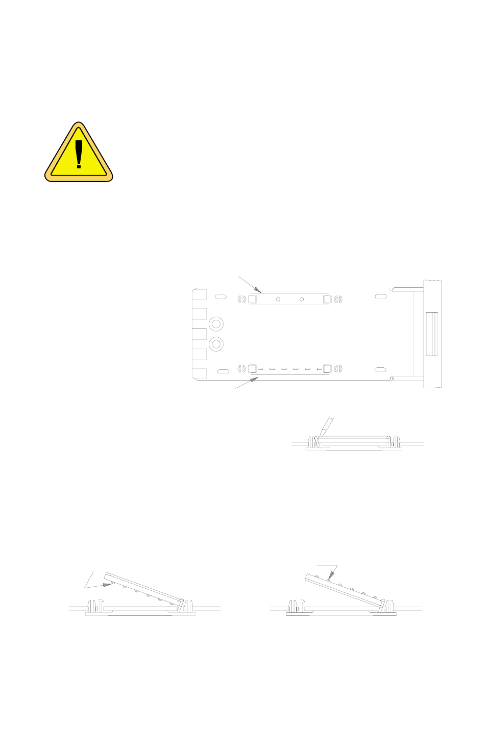
Locate the desired logic jumper strip on the left printed circuit board. The
OUTPUT A jumper
strip is always lo-
cated near the top
edge
3.
To remove the logic
jumper strip, carefully
insert a small flat
blade screwdriver be-
tween the retaining
clip and the jumper
at one end of the
jumper strip. Apply slight pressure to
move the clip away from the jumper end
until it is released, then lift it up and out of
the clip.
4.
To re-install the jumper strip, hold it with the spring contacts in the desired
position. Face springs up for SSR or RELAY outputs, or face springs down
for LOGIC outputs. Insert one end of the jumper strip under the retaining
clip and press the other end down until the remaining clip engages the
jumper.
5.
To avoid any damage, recheck the jumper installation and the housing rear
terminal panel output wiring.
6.
Replace the instrument into its housing.
OUTPUT A SET FOR LOGIC TYPE OUTPUT
OUTPUT B SET FOR SSR or RELAY TYPE OUTPUT
SLIGHT PRESSURE TO RELEASE
RETAINING CLIP
INSTALLING JUMPER FOR
LOGIC TYPE OUTPUT
INSTALLING JUMPER FOR
SSR or RELAY TYPE
OUTPUT
SPRINGS UP
SPRINGS DOWN