Dwyer TFM-LP User Manual
Page 9
F-20-TF-L, pg. 9 of 30
a)
Overview
The TFP-LP and TFM-LP series provide a 0-5VDC and pulse output
proportional to the flow rate. This output may be connected to a display,
data acquisition system or voltmeter.
The TFP-LI and TFM-LI feature an integral display that provides a local flow
reading. These units also have a 0-5VDC analog output available. If
required, this may be connected to another display, data acquisition system
or voltmeter.
A stable D.C. power supply is required to operate the unit. The voltage and
current requirements depend on the configuration of the unit. Full details
may be found in the Specifications section of this manual.
Connecting wires should be as short as possible to avoid voltage drops.
Twisted 2 pair conductor cable should be used if the length of the power
wires is to be longer than 1 meter.
Units are supplied with an integral 4 pin connector. Connections to the unit
are made using a mating cable assembly or power adapter package as
detailed in the following sections (parts 4.b to 4.e of this manual). A
connector pin and wire color cross reference may also be found in
Appendix G (Page 27) of this manual.
b)
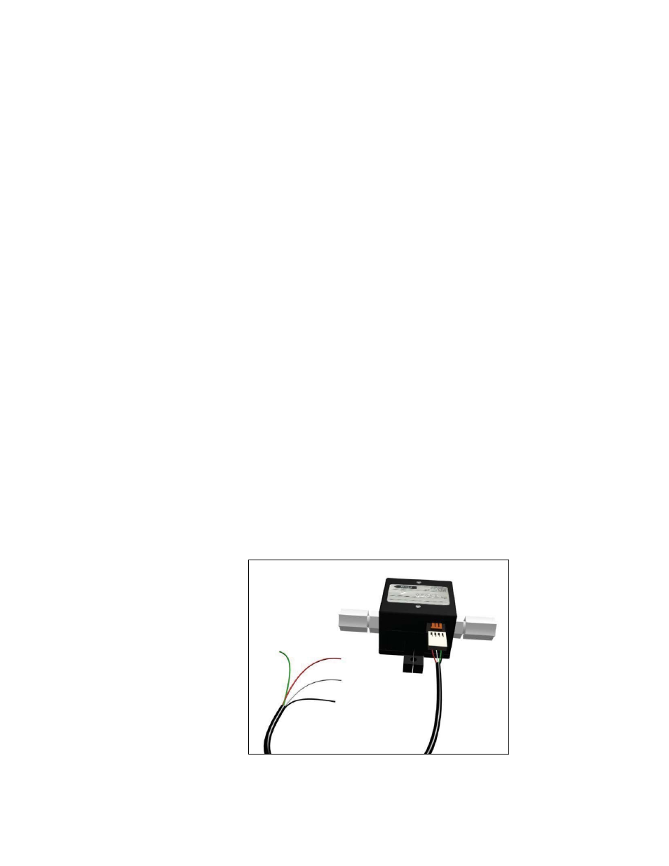
Connecting the Cable Assembly
The connector on the end of the cable assembly should be pushed into the
mating socket on the sensor taking care to ensure that it is the correct way
up.
Connecting the Cable Assembly
(All models similar)
Electrical Connections are made to the cable assembly as detailed in the
following sections.