Dwyer TFM-LP User Manual
Page 4
F-20-TF-L, pg. 4 of 30
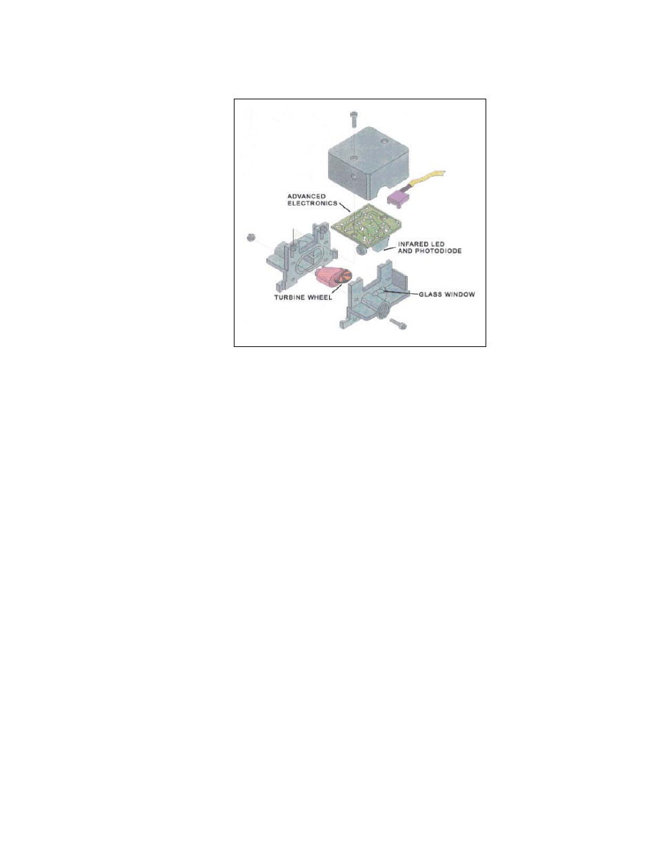
Wheel flow sensor design. This proven design minimizes zero drift while
maintaining fast response and linear outputs with virtually no maintenance.
Patented technology measures flow using a miniature turbine wheel similar
in size to a U.S. dime (16 mm diameter, 0.75 mm thick). The micro-turbine
wheel is supported on a very small sapphire shaft that is held in position by
two sapphire bearings. The micro-turbine assembly is so light that it virtually
floats in the liquid. This relieves force on the bearings and almost eliminates
wear.
As flow passes through the flow sensor, a precision machined nozzle directs
the fluid onto the very small teeth of the micro-turbine wheel. This causes the
wheel to spin at a speed proportional to the flow rate.
The micro-turbine wheel has alternating white and black sections evenly
spaced on one side of the wheel. An infrared light beam is directed onto the
wheel. As the wheel rotates the infrared beam is reflected off each white
section. The reflected beam is detected by a phototransistor that converts the
reflections into electrical pulses. As the wheel spins faster the pulse rate
increases. Processing circuitry provides analog and/or pulse output that are
linearly proportional to the flow rate
When the wheel stops (under zero flow conditions), no pulses are
generated. Consequently, zero drift is not possible and zero adjustments are
never required.
Every unit is supplied with a calibration certificate detailing the results
obtained during calibration. Units are calibrated using deionized water as
the reference media. Flowing liquids with different specific gravities or
viscosities may affect the calibration.