Optimiser – Caleffi 1522 User Manual
Page 9
9
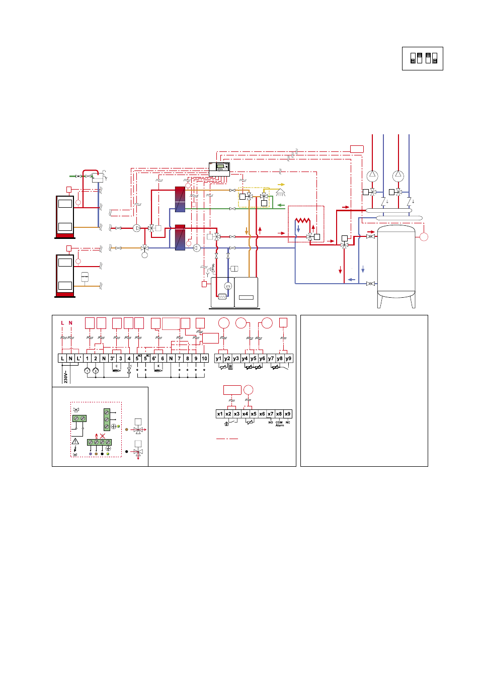
Operating principle
The 1522 series regulator automatically manages a system composed of a solid fuel generator, gas integration boiler (for heating and domestic
hot water), inertial water storage in parallel on the heating system and instantaneous domestic hot water production by means of a plate heat
exchanger.
When the minimum working temperature of the solid fuel generator has been reached (as detected by probe S1), the regulator starts pump P1,
diverts valve V1 to connect the heat exchanger to the system and starts pump P2. With the solid fuel generator off or not yet at working
temperature, the regulator starts the integration boiler by means of contact C, stopping pumps P1 and P2 and diverting diverter valve V1 to the
boiler.
In the case of solid fuel generator overtemperature, the regulator sends the flow rate of the secondary circuit either to the system (in the
presence of room thermostat demand) or to an optional dissipation system, if present.
When a domestic user tap is opened, on a signal from flow switch F, the regulator operates priority valve V3 to produce instantaneous hot water
with the solid fuel generator only if the latter is already at working temperature. Probe S3 reads the water temperature at the domestic heat
exchanger outlet and, if necessary, the regulator integrates the domestic hot water by supplying it to the gas boiler by means of a diverter valve
(not supplied in the pack, e.g. SOLARINCAL kit code 265359).
The inertial water storage in parallel is managed in accordance with the logic described on page 6. By means of diverter valve V5 (not supplied
in the pack, e.g.: Caleffi 6443..3BY series + relay box code F29525) the regulator manages all phases of loading and unloading of the water
storage, which is kept closed only if the gas boiler has been activated. Connection of the parallel water storage to the rest of the system is
managed by the regulator by comparing the temperature readings of probes S1 (located on the solid fuel generator flow pipe), S5 (located on
the heat exchanger return line) and S4 (located on the parallel water storage). For probe S5 it is advisable to use the following working set-
points: 45°C for radiator systems, 30°C for radiant panel systems. The gas boiler starts when the solid fuel generator temperature is below the
minimum working temperature TSG (measured by probe S1) and the heat exchanger return temperature TR (measured by probe S5) is 5°C
below the value set on the regulator (TR set, fixed hysteresis value 5K).
-
+
Optimiser
V5
V4
M
M
D
K
S1
K
S1
D
D
T
P1
V3
P2
C
V1
F
S3
RT
D
SOLARINCAL
M
D
S5
S5
S4
K
C
V4
SOLAR
INCAL
P1 P2
V1
V3
RT
S3
F
S1
V5
F29525
S4
Regulator 152200
V5=Zone valve 6443..3BY
Com.
Relè 1 VA
8 VA
L
N
N
10
Wiring diagram of F29525
relay box - 230 V ˜ 50 Hz
Domestic
water
system
DHW
Optional
dissipator
Heating
system
Open vessel
Closed vessel
Wiring diagram
L Live
L’ Live jumper
1 ON pump P1
2 ON pump P2
N Neutral common
3’ Gas generator C
3 Gas generator C
5
NO
ON diverter valve V3
for domestic priority
5
NC
ON diverter valve V3
to heating system
6’ Solid fuel generator K
6 Solid fuel generator K
N Neutral common
7 SOLARINCAL with flow
to user
8 SOLARINCAL with flow
to domestic integration
10 ON valve V5 to load the
parallel water storage
y1 Probe S1
y2 Probe S1
y4 Probe S5
y5 Probe S5 and
S4 common
y6 Probe S4
y8 ON flow switch F
y9 ON flow switch F
x2 Room thermostat
RT contact
x3 Room thermostat
RT contact
x4 Probe S3 on domestic
exchanger outlet
x5 Probe S3 on domestic
exchanger outlet
wiring to be made
N Neutral
4 ON diverter valve V1
9 On diverter valve V4
SOLID FUEL
GENERATOR
INERTIAL
WATER
STORAGE
IN PARALLEL
HEATING
BOILER
SOLID FUEL
GENERATOR
V5
D
V5
D
ON
1 2 3 4
Program 6 (software code PR85)
Heating, instantaneous domestic hot water + management of inertial water storage in parallel on the
heating system.
Number of probes utilised: 4
Probe S1 located on solid fuel generator flow
Probe S3 (not supplied in the pack) located on domestic heat exchanger outlet
Probe S5 located on heat exchanger inlet on secondary side of circuit
Probe S4 located on the inertial water storage in parallel on the heating system