Optimiser – Caleffi 1522 User Manual
Page 8
8
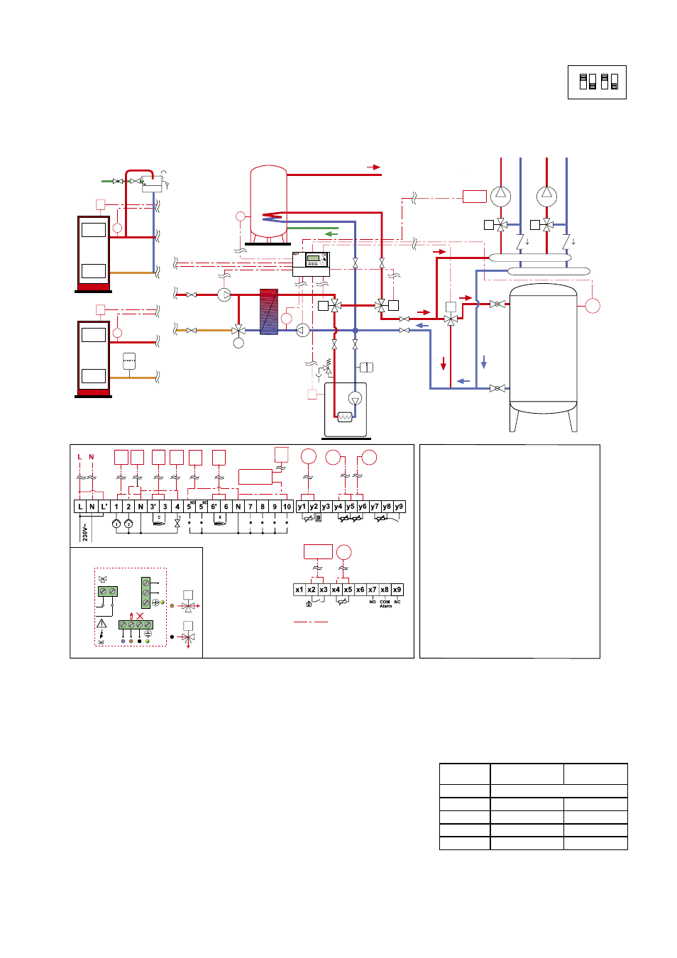
Operating principle
The 1522 series regulator automatically manages a system composed of a solid fuel generator, integration gas boiler, inertial water storage in
parallel on the heating system and domestic hot water production by means of a water storage.
When the minimum working temperature of the solid fuel generator has been reached (as detected by probe S1), the regulator starts pump P1,
diverts valve V1 to connect the heat exchanger to the system and starts pump P2. With the solid fuel generator off or not yet at working
temperature, the regulator starts the integration boiler by means of contact C, stopping pumps P1 and P2 and diverting diverter valve V1 to the boiler.
In the case of a solid fuel generator overtemperature, the regulator sends the flow rate of the secondary circuit either to the system (in the
presence of a room thermostat demand) or to the domestic water storage if it is not yet at
operating temperature or lower than the limit temperature. The domestic water storage is
maintained at operating temperature by probe S2 and priority diverter valve V2. The regulator
performs thermal disinfection of the domestic water storage in accordance with four
user-selectable preset programs, keeping it for two hours at the disinfection temperature
“Legio.-Temp”, settable in the range 40–75°C. The user can anyway add further disinfection
periods (designated TP points in the menu).
The inertial water storage in parallel is managed in accordance with the logic described on
page 6. By means of diverter valve V5 (not supplied in the pack, e.g.: Caleffi 6443..3BY series
+ relay box code F29525) the regulator manages all phases of loading and unloading of the
water storage, which is kept closed only if the gas boiler has been activated. Connection of the parallel water storage to the rest of the system
is managed by the regulator by comparing the temperature readings of probes S1 (located on the solid fuel generator flow pipe), S5 (located
on the heat exchanger return line) and S4 (located on the parallel water storage). For probe S5 it is advisable to use the following working
set-points: 45°C for radiator systems, 30°C for radiant panel systems. The gas boiler starts when the solid fuel generator temperature is below the
minimum working temperature TSG (measured by probe S1) and the heat exchanger return temperature TR (measured by probe S5) is 5°C below the
value set on the regulator (TR set, fixed hysteresis value 5K).
-
+
Optimiser
V5
F29525
K
V2
C
P1 P2
C
V1
RT
S2
S1
S5
S4
V5
K
S1
K
S1
M
M
D
D
T
P1
V2
P2
C
V1
S2
RT
D
S4
S5
Com.
Relè 1 VA
8 VA
L
N
N
10
Wiring diagram
L Live
N Neutral
L’ Live jumper
1 ON pump P1
2 ON pump P2
4
ON diverter valve V1
5
NO
ON diverter valve V2
for domestic priority
5
NC
10 ON valve V5 to load
the parallel water
storage
y1 Probe S1
y2 Probe S1
y4 Probe S5
Probe S4
y5 Probe S5 and
S4 common
y6
x2 Room thermostat
RT contact
x3 Room thermostat
RT contact
x4 Domestic water
storage probe S2
x5 Domestic water
storage probe S2
wiring to be made
Heating
system
Domestic
water
system
DCW
DHW
Open vessel
Closed vessel
6 Solid fuel
generator K
3 Gas generator C
3’ Gas generator C
N
Neutral common
6’ Solid fuel
generator K
N
Neutral common
SOLID FUEL
GENERATOR
SOLID FUEL
GENERATOR
INERTIAL
WATER
STORAGE
IN PARALLEL
HEATING
BOILER
D
Wiring diagram of F29525
relay box - 230 V ˜ 50 Hz
Regulator 152200
V5=Zone valve 6443..3BY
V5
D
V5
D
ON
1 2 3 4
Program
Disinfection
day
Disinfection
time slot
0
No disinfection
1
Mon.
2-4
2
Sat.
10-12
3
Sun.
10-12
4
Mon. and Wed.
2-4
Program 5 (software code PR84)
Heating, domestic hot water with storage + management of inertial water storage in parallel on the heating system.
Number of probes utilised: 4
Probe S1 located on solid fuel generator flow
Probe S2 (not supplied in the pack) located on domestic water storage
Probe S5 located on heat exchanger inlet on secondary side of circuit
Probe S4 located on the inertial water storage in parallel on the heating system