Figure 24 – Badger Meter B3000 User Manual
Page 26
Compact Digital Flow Monitor, Model B3000
Page 26
March 2014
Set Point 1 SetPt 1
Extended Function
The set point is the flow value at which the output transistor changes state It is set using the same units as the rate units
are entered
JP1
JP2
JP3
Input
Total P
ulse
Sig
nal
P1
Freq. In
4-20mA
Iso Total Pluse
TR_B
TR_A
RS485 Gnd
Setpoint 1
Setpoint 2
Gnd
+
–
+
–
+
–
Total Reset
OC Total Pluse
Signal Gnd
TB1
Mag
Pulse
Iso
OC
Low
High
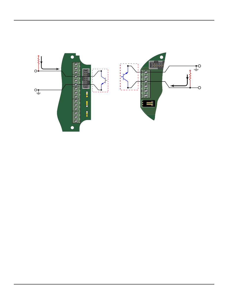
Open Collector
Control Output
1 and 2
2.2…10K
Pull-up
Resistor
V
CC
Internal
100 mA
Maximum
TR_B
TR_A
RS485 Gnd
Setpoint 1
Setpoint 2
Gnd
+
–
P2
3.6Vdc
Battery
TB1
P1
P1
Internal
Open Collector
Control Output
1 and 2
2.2…10K
Pull-up
Resistor
V
CC
100 mA
Maximum
Figure 24: Set point output (NEMA 4X)
Figure 25: Set point output (Ex-Proof))
At the SetPt 1 prompt, press ENTER The most significant digit of the current setting begins to flash If the current setting is
correct, press ENTER to advance to the next parameter
If the current setting requires a change, press
► to advance to the first digit of the required set point value Once the correct
place is reached use
▲ to increment the digit until it matches the first number of the required set point Use ► to advance to
the next digit of the required set point value then use
▲to increment the display digit until it matches the next digit of the
required set point Repeat this step for the all the digits of the set point and then press ENTER to save the new set point and
advance to the next parameter
Hysteresis 1 HystSP1
Extended Function
Hysteresis is used to modify how the output transistor reacts around a set point by taking recent history into account
Hysteresis prevents an output from turning on and off rapidly when the programed flow rate is at or very near the set point
For example, a low flow alarm is set to activate when the flow falls below a pre programed point When the flow is reduced to
the set point, even minute changes of flow above the set point turns the output off disabling the alarm Without hysteresis, if
the flow rate fluctuates slightly above and below the set point the output rapidly cycle between on and off states
Another example is a thermostat controlling a heater The thermostat turns the heater on when the temperature drops below
“A” degrees, but won’t turn it off until the temperature rises above “B” degrees The temperature between “A” and “B” is know as
the hysteresis Thus the on/off output of the thermostat to the heater when the temperature is between “A” and “B” depends
on the “history” of the temperature This prevents rapid switching on and off as the temperature drifts around the set point
Refer to the graphical representation of the hysteresis setting as shown in
. The hysteresis value is set using the same
units as the rate units are entered
At the HystSP1 prompt, press ENTER The most significant digit of the current setting begins to flash If the current setting is
correct, press ENTER to advance to the next parameter
If the current setting requires a change, press
► to advance to the first digit of the required hysteresis value Once the correct
place is reached use
▲ to increment the digit until it matches the first number of the required hysteresis Use ► to advance
to the next digit of the required hysteresis value then use
▲ to increment the display digit until it matches the next digit of
the required hysteresis Repeat this step for the all the digits of the hysteresis and then press ENTER to save the new hysteresis
and advance to the next parameter