Installation, Connecting the b3000 to a frequency output device, Installation 10 – Badger Meter B3000 User Manual
Page 10
Compact Digital Flow Monitor, Model B3000
Page 10
March 2014
INSTALLATION
Connecting the B3000 to a Frequency Output Device
Most turbine flow sensors produce a frequency output that is directly proportional to the volumetric flow through the sensor
There are, however, different output waveforms that can be presented to the display device depending on the transducer that
converts the mechanical motion of the turbine into an electrical signal
The B3000 monitor has two jumpers that are used to set the type of signal and the minimum amplitude of the signal that it
accepts The first thing to established is the type of output provided by the flow sensor The outputs almost always fall into
one of two types
Type 1 – This is the unaltered frequency signal coming from an un-amplified magnetic pickup This signal is
normally a sine wave in appearance and the amplitude of the waveform varies with the flow Small turbines have
comparatively small rotating masses so they produce a smaller amplitude waveform and higher frequencies than
larger turbine sensors
Type 2 – The frequency signal from the transducer is amplified, wave shaped or both to produce a waveform of a
specified type and amplitude Most amplified transducers output a square wave shape at one of many standard
amplitudes For example a popular amplified output is a 10V DC square wave
If the flow sensors output signal is type 1, the minimum amplitude of the frequency output must also be determined The
B3000 has a high or low signal sensitivity setting High signal sensitivity (30 mV) is used with low amplitude (usually small)
turbine flow sensors The low signal sensitivity setting (60 mV) is typically used for larger turbines and amplified transducers
(see
OTE:
N
The high signal sensitivity setting is used where the minimum signal amplitude is below 60 mV Setting the sensitivity
lower than necessary opens the instrument up to a greater possibility of noise interference
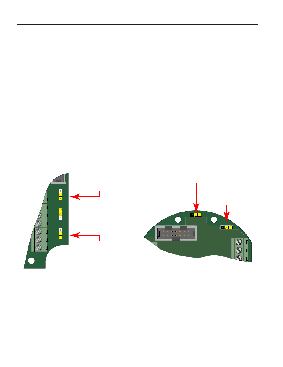
JP1
JP2
JP3
Input
Total P
ulse
Sig
nal
TB1
Mag
Pulse
Iso
OC
Low
High
Input Waveform Selection
(Magnetic Pickup Selection Shown)
Input Signal Level Selection
(Low Signal Sensitivity (60 mV) Selection Shown)
Freq. In
+
–
Gnd
JP1
Input
Mag
Pulse
JP2
TB2
TB1
P1
Signal
Low
High
P1
Input Waveform Selection
(Magnetic Pickup Selection Shown)
Input Signal Level Selection
(Low Signal Sensitivity (60 mV) Selection Shown)
Figure 3: Input jumper settings (NEMA 4X)
Figure 4: Input jumper settings (Ex-Proof)
Once the type of waveform and input signal level (amplitude) are determined the jumpers on the B3000 circuit board are set
For typical variable reluctance magnetic pickups the waveform selection jumper should be set for Mag The setting for
the input level must be determined from looking at the magnetic pickup specifications If the minimum amplitude at the
minimum rated flow is greater than 60 mV use the low signal sensitivity jumper position (see
and
If the minimum signal level is below 60 mV use the high signal sensitivity jumper position
Again all B3000 flow monitors come pre-configured from the factory, if ordered with a Blancett flow sensor