Power connections, Standard, Power connections 12 – Badger Meter B3000 User Manual
Page 12: Standard 12, Caution
Compact Digital Flow Monitor, Model B3000
Page 12
March 2014
POWER CONNECTIONS
Standard
The power supply used in the B30A/B/X/Z is an internal lithium 3 6V DC “D” cell that will power the monitor for about six years
when no outputs are used The monitor can also get power from a 4-20 mA current loop (see
) If the
current loop is used a sensing circuit within the monitor detects the presence of the current loop and disconnects the battery
from the circuit The B30L/M/W/ versions use loop power only and the B30S uses solar power only
JP1
JP2
JP3
Input
Total P
ulse
Sig
nal
P1
Freq. In
4-20mA
Iso Total Pluse
TR_B
TR_A
RS485 Gnd
Setpoint 1
Setpoint 2
Gnd
+
–
+
–
+
–
Total Reset
OC Total Pluse
Signal Gnd
TB1
Mag
Pulse
Iso
OC
Low
High
4-20 mA
Current Loop
(10…28V DC)
Load
10…28V DC
Freq. In
4-20mA
Iso Total Pluse
+
–
+
–
+
–
Total Reset
OC Total Pluse
Signal Gnd
TR_B
TR_A
RS485 Gnd
Setpoint 1
Setpoint 2
Gnd
+
–
P2
3.6Vdc
Battery
JP3
Total Pulse
ISO
OC
JP1
Input
Mag
Pulse
JP2
TB2
TB1
P1
Signal
Low
High
P1
4-20 mA
Current Loop
(10…28V DC)
Load
10…28 VDC
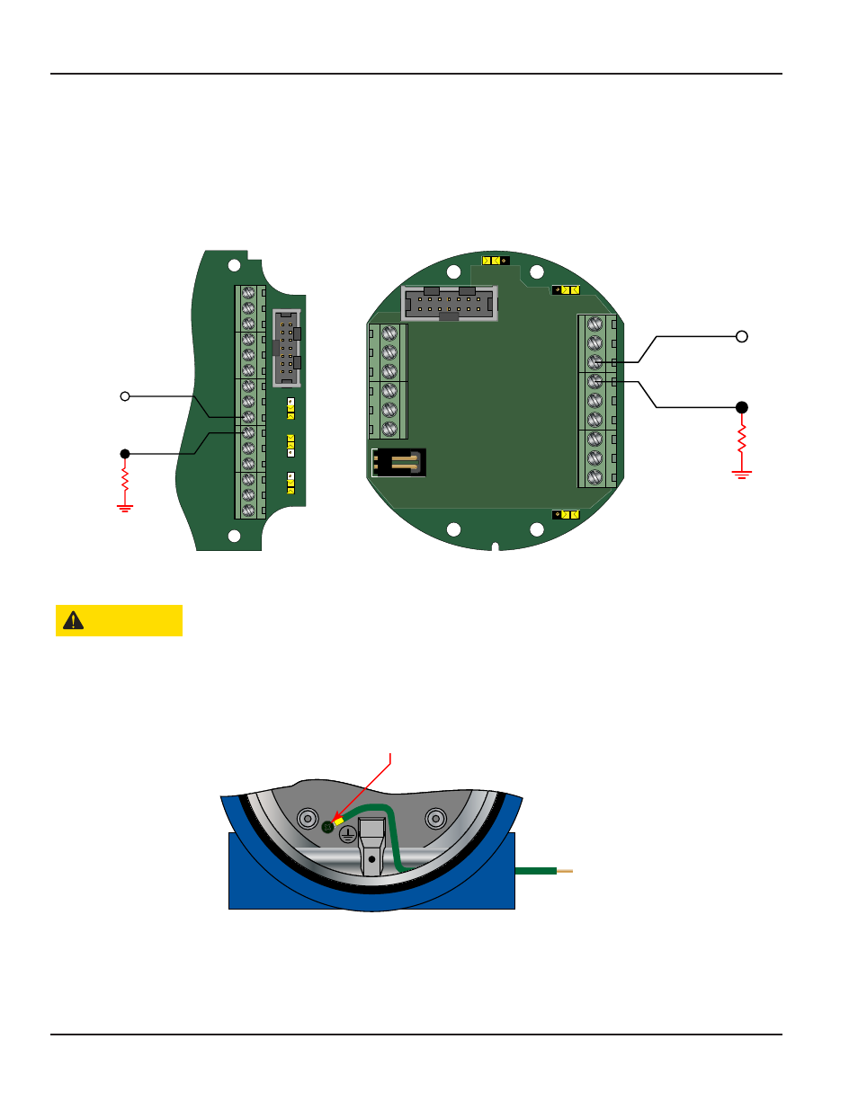
Figure 9: Loop power connections (NEMA 4X)
Figure 10: Loop power connections (Ex-Proof)
CAUTION
GROUNDING FOR THE EXPLOSION PROOF ENCLOSURE IS NECESSARY. THE EXPLOSION PROOF ENCLOSURE IS
PROVIDED WITH A GROUNDING SCREW ON THE INSIDE OF THE ENCLOSURE. THE CONDUCTOR USED FOR GROUNDING
MUST BE OF A WIRE GAGE EQUAL TO OR GREATER THAN THE SIGNAL WIRES BEING USED. SEE
.
The explosion proof enclosure is provided with a grounding screw on the inside of the enclosure The conductor used for
grounding must be of a wire gage equal to or greater than the signal wires being used
To Earth Ground
Figure 11: Required grounding for Ex-proof enclosure