Power supply – Badger Meter B3000 User Manual
Page 23
Programming Manual
Page 23
March 2014
Flow at 20 mA Fl=20mA
Basic Function
When the display is operated using loop power, the flow rate that corresponds to 20 mA must be set This setting normally
represents the maximum rate of the flow sensor connected to the display but other entries are possible
At the Fl=20mA prompt, press ENTER The current setting will begin to flash If the current setting is correct, press ENTER to
advance to the next parameter If the current setting requires a change, use
▲ to increment the display digit until it matches
the first digit of the required maximum flow value Next press
► to advance to the next digit and using ▲ to increment the
second display digit until it matches the second digit of the
required value Repeat this step until the maximum flow at 20
mA is entered Press ENTER to save the new flow value
4-20 mA Calibration 4-20Cal
Extended Function
This menu item allows the fine adjustment of the Digital to
Analog Converter (DAC) that controls 4-20 mA output The
4-20 mA output is calibrated at the factory and under most
circumstances does not need to be adjusted If the output needs
to be adjusted for any reason the 4-20 mA calibration procedure
is used
The DAC used in the B3000 is an twelve bit device so the valid
entries range from 0…4095
4 mA Adjustment 4mA Out
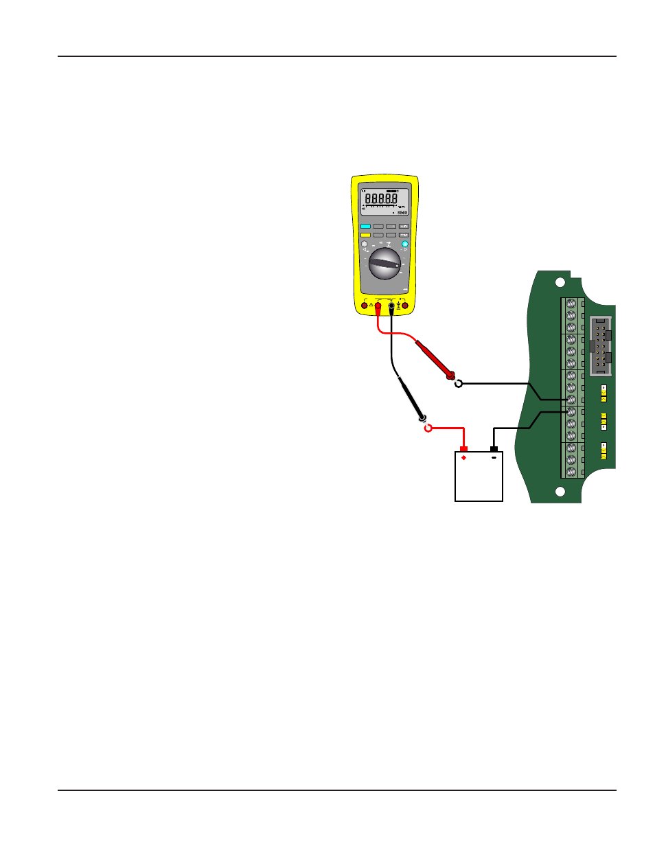
To set the 4 mA value, connect an ammeter in series with the loop
power supply as shown in
At the 4-20Cal prompt, press ENTER
The display will now show a steady NO indication Press
▲ to change to
a YES display and press ENTER The 4 mA DAC setting is typically between
35…50 Using
▲ and ► while monitoring the ammeter, adjust the 4 mA value
to obtain a 4 mA reading on the ammeter The
▲ increases the DAC value
and ► decreases the DAC value. When a steady 4 mA reading is obtained on
the ammeter, press ENTER to lock in this value and move to the 20 mA adjustment
Figure 23: 4-20 mA calibration setup
20 mA Adjustment 20mAOut
The 20 mA adjustment is performed using the same procedure as the 4 mA adjustment While monitoring the ammeter,
adjust the 20 mA DAC value to obtain a 20 mA reading The
▲ increases the DAC value and ► decreases the DAC value.
When a steady 20 mA reading is obtained on the ammeter, press ENTER to lock in this value and move to the next parameter
4-20 mA Test 4-20Tst
The B3000 monitor contains a diagnostic routine that allows the simulation of mA output values between 4…20 to check
output tracking At the 4-20 TEST prompt the current is shown as a flashing number Use
▲ to increase the simulated mA
output in increments of 1 mA The
► decreases the mA output. The ammeter should track the simulated mA output If a
4-20 mA test is not necessary, press ENTER to move to the next parameter
OTE:
N
Pressing ENTER when the monitor is in test mode will exit the test mode and move on to the next
programming parameter
P1
Freq. In
4-20mA
Iso Total Pluse
TR_B
TR_A
RS485 Gnd
Setpoint 1
Setpoint 2
Gnd
+
–
Total Reset
OC Total Pluse
Signal Gnd
TB1
Mag
Pulse
Iso
OC
Low
High
+
+
–
–
Input
Total P
ulse
Sig
nal
JP1
JP2
JP3
4-20 mA
Current Loop
(11 to 30 VDC)
POWER
SUPPLY
10A MAX
FUSED
400mA
FUSED
CAT III
1000V
HOLD
MIN MAX
REL
Hz % ms
RANGE
AutoHOLD FAST MIN MX
LOGGING
YES
CANCEL
SAVE
NO
SETUP
µA
mA
A
W
V
TEMPERATURE
COM
OFF
nS
W
VIEW MEM
CLEAR MEM
V
dB
mV
dB
ac+dc
V
ac+dc
A
mA
mV
ac+dc
mA
A
µA
ac+dc
µA
°C
°F
MEM
HM
MS
51000
AUTO MANUAL
%
FA S T M A X M I N AV G
0
0
LOG
HOLD