SUOMY D2O User Manual
Page 16
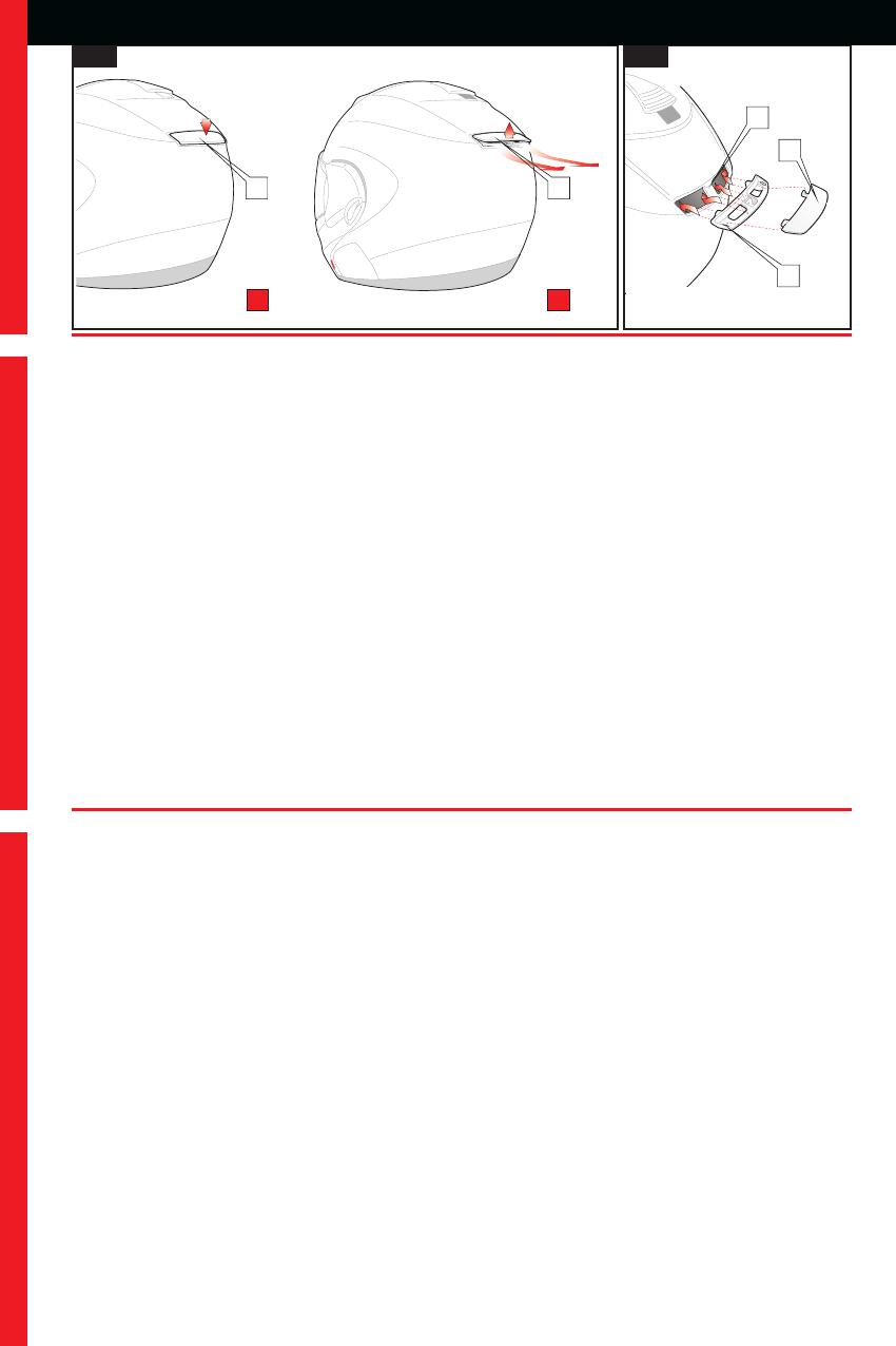
BACK AIR DEFLECTOR
Operation – see fig. 4A
The air flow coming in from the back part of the helmet can be adjusted by using the deflector (A) itself on
the back part of the shell:
-
Position (X)
: deflector (A) closed - air intake completely closed.
-
Position (Y)
: deflector (A) open - air intake completely open.
Removal – see fig. 4B
The back deflector is fixed to the shell through a click-in mechanism, to remove it follow this procedure: set
it in the completely open position. Remove the deflector (A) by releasing one of the two sides (left or right);
after releasing the one side remove the other. Afterwards remove the deflectorʼs fixing seat (B). If it is difficult
to remove, use a tool (for ex. a screwdriver) and lever on the sides. During this operation protect the point of
contact of the tool with the shell with a cloth to avoid damaging or scratching the paint. When inserting the
tool to remove the base, be very careful because the base of very close to the protection polystyrene.
# Do not put the tool in-between the edge of the back deflector and the shell.
After removing, before replacing the parts, remove any dirt residues from the shell.
Fitting the mechanism – see fig. 4B
The back deflector is fixed to the shell through a click-in mechanism. To put it back into place follow this pro-
cedure:
# Before applying, carefully clean the surfaces where the device has to be applied to.
Verify the positioning of the details by applying them on the shell in the correct position. The back deflector
must be positioned in the proper seat (C) on the back part of the shell. Verify that the side and upper edges
of the deflector adhere to the ribbing on the shell.
Position the part on the shell in the correct position, by pressing evenly on the edges; perform this operation
from the front part (towards visor) to the back part (towards bottom of shell) and never vice versa. Position
deflector until it clicks into position.
SPOILER ARRIÈRE
Fonctionnement – voir fig. 4A
Le flux dʼair sortant par la partie postérieure du casque peut être réglé en agissant sur le curseur (A) situé
sur la partie postérieure de la calotte :
-
Position (X)
: spoiler fermé – prise dʼair complètement fermée.
-
Position (Y)
: spoiler ouvert– prise dʼair entièrement ouverte.
Démontage – voir fig. 4B
Le spoiler arrière est fixé à la calotte au moyen dʼun mécanisme à encastrement, pour l'ôter, procéder ainsi
: placer le spoiler en position dʼouverture totale. Ôter le spoiler en désinsérant dʼabord lʼun des deux côtés
(Gauche ou Droit) ; une fois le côté choisi désinséré, enlever lʼautre de son emplacement. Ôter ensuite la base
de fixation (B) du spoiler. Dans le cas où me démontage sʼavérerait difficile, il est possible dʼutiliser un outil
(un tournevis par exemple) en lʼenfilant dans une des ouvertures postérieures dans les trous dʼentrée dʼair
et en faisant levier sur la calotte. Pendant cette opération, protéger le point dʼappuis de lʼoutil sur la calotte
avec un chiffon de façon à ne pas provoquer de dommages ou dʼéraflures sur la couche de verni.
# Ne jamais utiliser lʼoutil en insérant directement la pointe de celui-ci entre le bord du spoiler et la calotte.
Une fois le démontage effectué et avant de procéder au montage de lʼaccessoire, ôter les éventuels résidus
dʼadhésif ou de saleté accumulée sur la surface de la calotte.
Remontage – voir fig. 4B
Le spoiler arrière est fixé à la calotte au moyen dʼun mécanisme à encastrement, pour le remonter, procéder
ainsi :
# Avant de procéder à lʼapplication, nettoyer soigneusement les surfaces sur lesquelles doit être appliquée
la pièce.
Vérifier le positionnement des pièces en les appliquant sur la calotte dans leurs positions correctes. Le spoiler
arrière doit être positionné à lʼemplacement spécial (C) situé sur la partie arrière de la calotte, en faisant bien
attention de faire adhérer les bords latéraux et le bord supérieur du spoiler aux nervures de la calotte.
Positionner la pièce sur la calotte dans la position correcte en exerçant une pression uniforme sur les bords;
16
USERʼS INSTRUCTIONS INSTRUCTIONS DʼUTILISATION ISTRUZIO
GB
FR
4A
4B
X
Y
A
A
B
C
A