Set-up, Rear panel and terminals, Power – SHIMPO DT-5TS User Manual
Page 5: Sensor connection, Self-test
5
Set-Up
Power
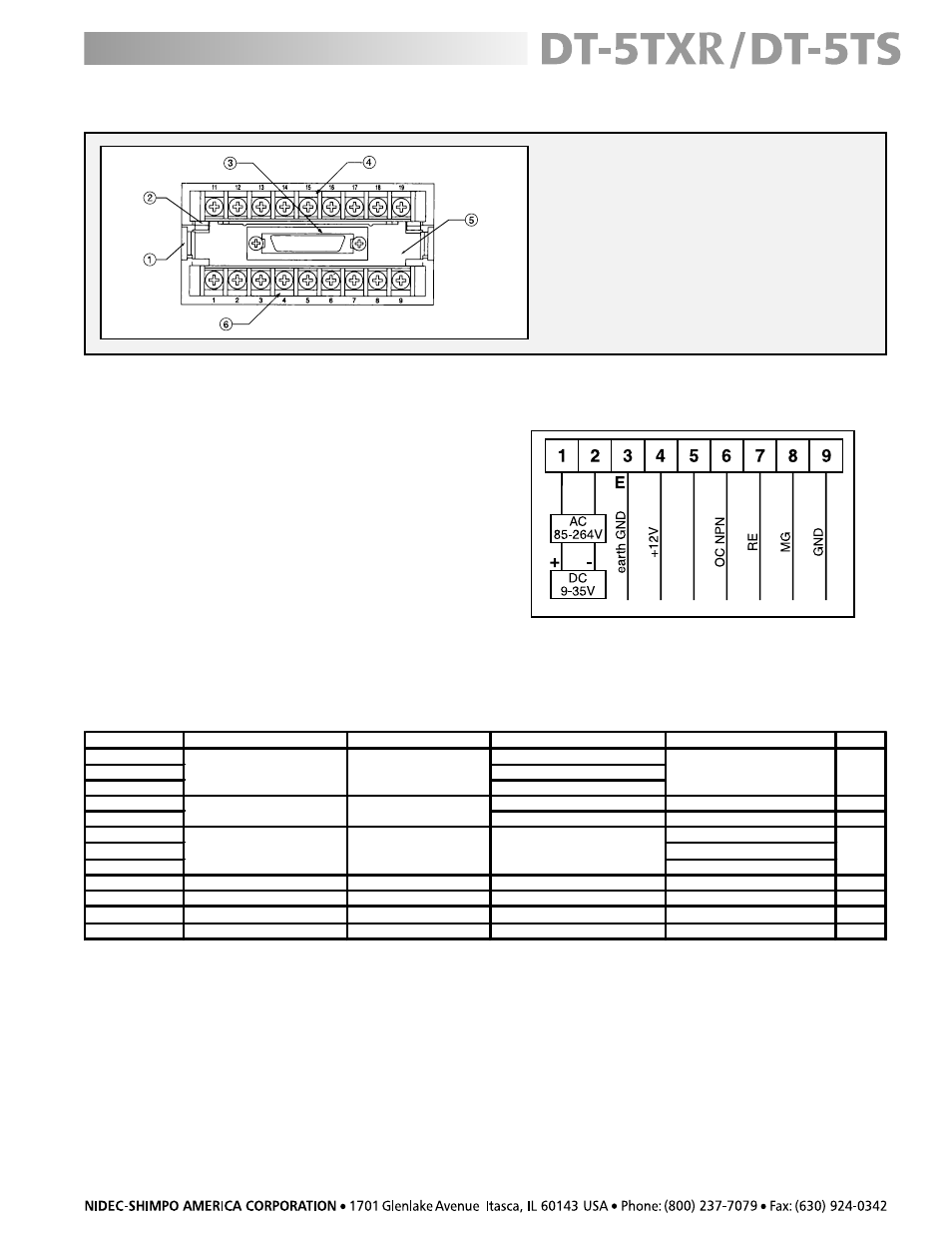
Refer to diagram 1 (right) for location of the terminals.
AC Models
Apply 85 – 264 VAC, 50/60 Hz between terminals 1 and 2.
DC Models
Apply 9 –35 VDC between terminals 1 (positive) and 2
(negative) on the main terminal block.
After proper power (AC or DC) is applied to the unit
and before any sensor is connected, the LED display
will light up.
Sensor Connection
Use the chart below to determine how to connect the
DT-5TXR/DT-5TS to Shimpo sensors:
diagram 1
Self-Test
To confirm that all display LEDs are operating correctly, a self-test is recommended (see “Display and Keypad” section
for button locations):
1. Press and hold the MODE button for approximately 3 seconds; “0” will begin flashing until “-01-” appears on the
display.
2. Press any of the lower buttons (NUMERIC, NEGATIVE SIGN/DECIMAL POINT, BACKSPACE) to scroll through “-02-”,
“-03-” and “-04-” until “-99-” appears on the display.
3. Press the SET button to begin the self-test. The entire display will cycle through all digits, arrows, dashes, colons,
decimal points, etc.
4. When satisfied that all LED’s are operational, press the SET button to exit.
SENSOR
TYPE
TERMINAL NUMBER
FREQUENCY or RPM RANGE
OPERATION TEMPERATURE
FILTER
M
P
R
0
0
0
,
5
–
0
C
0
6
-
B
1
E
R
3
–
0
C
0
0
6
-
B
1
E
R
,000 RPM
1
–
0
C
0
0
0
1
-
B
1
E
R
,800 RPM
z
H
k
0
0
1
)
C
°
9
.
8
4
+
-
°
0
3
-(
F
°
0
2
1
+
-
°
2
2
-
z
H
0
5
2
–
0
5
2
6
-
S
C
M
F
°
1
3
1
+
-
F
°
3
1
-
z
H
3
3
3
–
0
5
5
6
-
S
C
M
(-25° - +55°C) 100 kHz
MP-10
-40° - +221°F (-40° - +105°C)
3030AN
-100° - +225°F (-73° - +107°C)
3070A*
-100° - +200°F (-73° - +104°C)
Contact Closure
Relay or Solenoid
Jumper 5 and 6 Connect 6,
z
H
0
2
z
H
0
2
<
9
BI2-S12
Open Collector NPN Proximity
4,6,
F
°
8
5
1
+
-
°
3
1
-
z
H
k
2
–
0
9
(-25° - +70°C)
100 kHz
z
H
k
0
3
)
C
°
0
7
+
-
C
°
0
2
-
(
F
°
8
5
1
+
-
F
°
4
-
z
H
k
8
–
0
9
,
7
,
4
y
ti
m
ix
o
r
P
g
n
i
h
c
ti
w
S
e
ri
w
-
3
G
-
E
S
z
H
k
0
1
)
C
°
0
6
+
-
°
5
5
-(
F
°
0
4
1
+
-
°
8
6
-
z
H
k
1
–
0
8
,
4
y
ti
m
ix
o
r
P
g
n
ih
c
ti
w
S
n
o
N
e
ri
w
-
2
G
-
2
J
D
* For hazardous locations
10 kHz
Retro-Reflective
Magnetic
Rotary Pulse Generator
30 kHz
3,8,9
)
C
°
0
5
+
-
°
0
1
-
(
F
°
2
2
1
-
°
4
1
9
,
7
,
4
4,6,9
Rear Panel and Terminals
NO. DESIGNATION
1. Lower Module Latch
2. Upper Module Latch
3. Lower Module Connector
4. Upper Module Terminal Block
5. Rear Cover
6. Main Terminal Block