Modules available for dt-5txr – SHIMPO DT-5TS User Manual
Page 15
15
Modules Available for DT-5TXR
A variety of modules are available to provide an array of
output and input options when using the DT-5TXR.
Most of the modules have either a “T” or “C” suffix in
the part number. The “T” indicates that the module’s
communication is wired through the terminal; the “C”
indicates that the module’s communication is wired
through a 36 pin connector (see “Rear Panel and
Terminals”, top of page 5). The only exception is the
DOP-BCD module, which is always wired through the
36-pin connector.
When purchasing a DT-5TXR with modules, please consult
the following:
Relay contact ratings: 250VAC (5A)
Resistive loads
30VDC (5A)
250VAC (2.5A)
Inductive loads
30VDC (2.5A)
NOTE: Relay contacts under above conditions have a life
of approximately 100,000 operations.
Using any of these part numbers ensures that the unit
will arrive assembled. Please consult the installation
manual (provided with individual modules) if removal/
replacement of the modules is required.
Upper Connector Options (with Terminal Block “T”)
DOP-FVTR (Analog output: 0-1VDC, 1-5VDC, 0-10VDC
and 4-20mA)
DOP-CPTR (Relay output: HI, GO, LO; 3 “C” type relays)
DOP-TRTR (NPN OC output: H (1), H (2), GO, L (1), L (2)
and ZERO)
DOP-RMTR (Ratio of two input functions)
Lower Connector Options (with Connectors “C”)
DOP-FVC (Analog output: 0-1VDC, 1-5VDC, 0-10VDC
and 4-20mA)
DOP-BCD (BCD output, TTL compatible)
All Module Combinations/Arrangements
The above modules are available for the DT-5TXR with
the following combinations:
DT-5TXR
DT-5TXR-FVTR
DT-5TXR-FVTR-BCD
DT-5TXR -CPTR
DT-5TXR-CPTR-FVC
DT-5TXR-CPTR-BCD
DT-5TXR-TRTR
DT-5TXR-TRTR-FVC
DT-5TXR-TRTR-BCD
DT-5TXR-RMTR
DT-5TXR-RMTR-FVC
DT-5TXR-RMTR-BCD
DT-5TXR-FVC
DT-5TXR-BCD
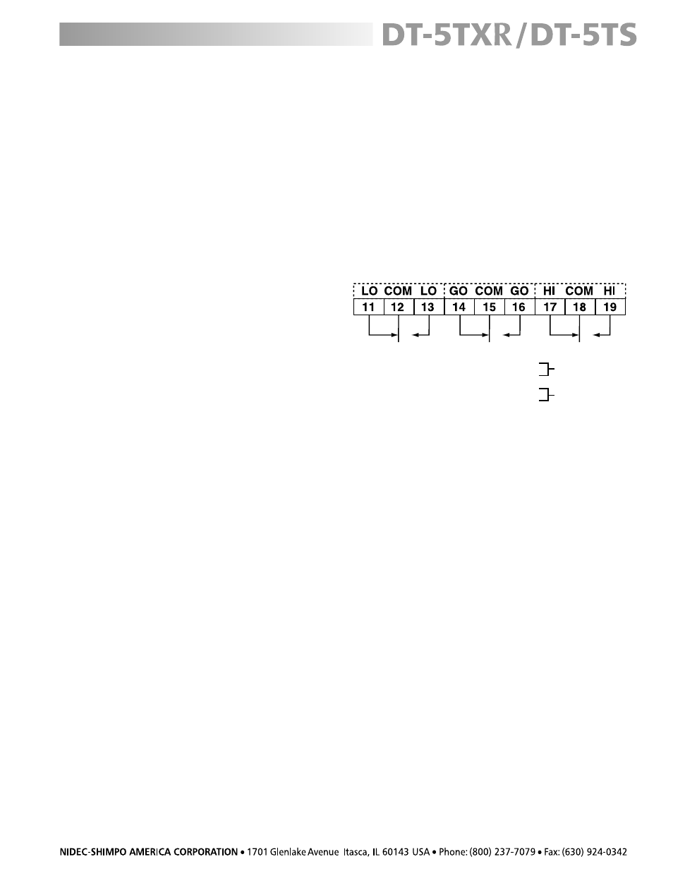
DT-5TXR with DOP-CPTR Module
DT-5TXR-CPTR
The model DT-5TXR-CPTR provides three “C” type relays that
can be used for setting two “set points”, one high and
one low. The third relay provides a GO signal and can be
used as such if needed.
Connect proper voltage (according to AC or DC model
configuration) between terminals 1 and 2 on the DT-
5TXR terminal block. Select high and low limits as described
in the “Setting High and Low Limits” section. If it is
assumed that the normal (GO) range is X, then the high
and low set points (limits) will react as follows:
Low set point
≤… X ≤… high set point