Front panel controls – Revo R4-8DVR4 User Manual
Page 11
4 & 8 Channel Digital Video Recorder
5
NO (Relay Alarm Output): Connect the device to the COM and NO (Normally Open) connector. NO is a relay
output which sinks 1A@30VDC (NO).
Connector Pin Outs:
Alarm In (1 to 8)
Alarm Inputs 1 to 8
GND
Chassis Ground
NO
Alarm Out (Normally Open)
COM
Common
Connecting to the RS-485 Port
The RS-485 connector can be used to control PTZ (pan, tilt, zoom) cameras. Connect TX+/RX+ or TX-/RX-
of the control system to the + or – (respectively) of the DVR. See the Camera Setup section in this chapter
of this manual and the PTZ camera manufacture’s manual for configuring the RS-485 connection.
Connector Pin Outs:
Master Unit
Slave Unit
+ → To → TX+/RX+
–
→ To → TX-/RX-
GND
→ To → GND
Connecting the DVR Power Cord
Connect the connector of the adaptor to the DVR, and connect the AC power cord to the adaptor and then
to the wall outlet.
WARNING: ROUTE POWER CORDS SO THAT THEY ARE NOT A TRIPPING HAZARD.
MAKE CERTAIN THE POWER CORD WILL NOT BE PINCHED OR ABRADED BY FURNITURE.
DO NOT INSTALL POWER CORDS UNDER RUGS OR CARPET.
THE POWER CORD HAS A GROUNDING PIN. IF YOUR POWER OUTLET DOES NOT HAVE
A GROUNDING PIN RECEPTACLE, DO NOT MODIFY THE PLUG. DO NOT OVERLOAD THE
CIRCUIT BY PLUGGING TOO MANY DEVICES IN TO ONE CIRCUIT.
CAUTION: Ensure the DVR is not near any heat source that could cause overheating.
CAUTION: The DVR does not have an internal fan so leave a clearance of at least 6 inches
near ventilation hole areas on each side panel of the unit for proper ventilation.
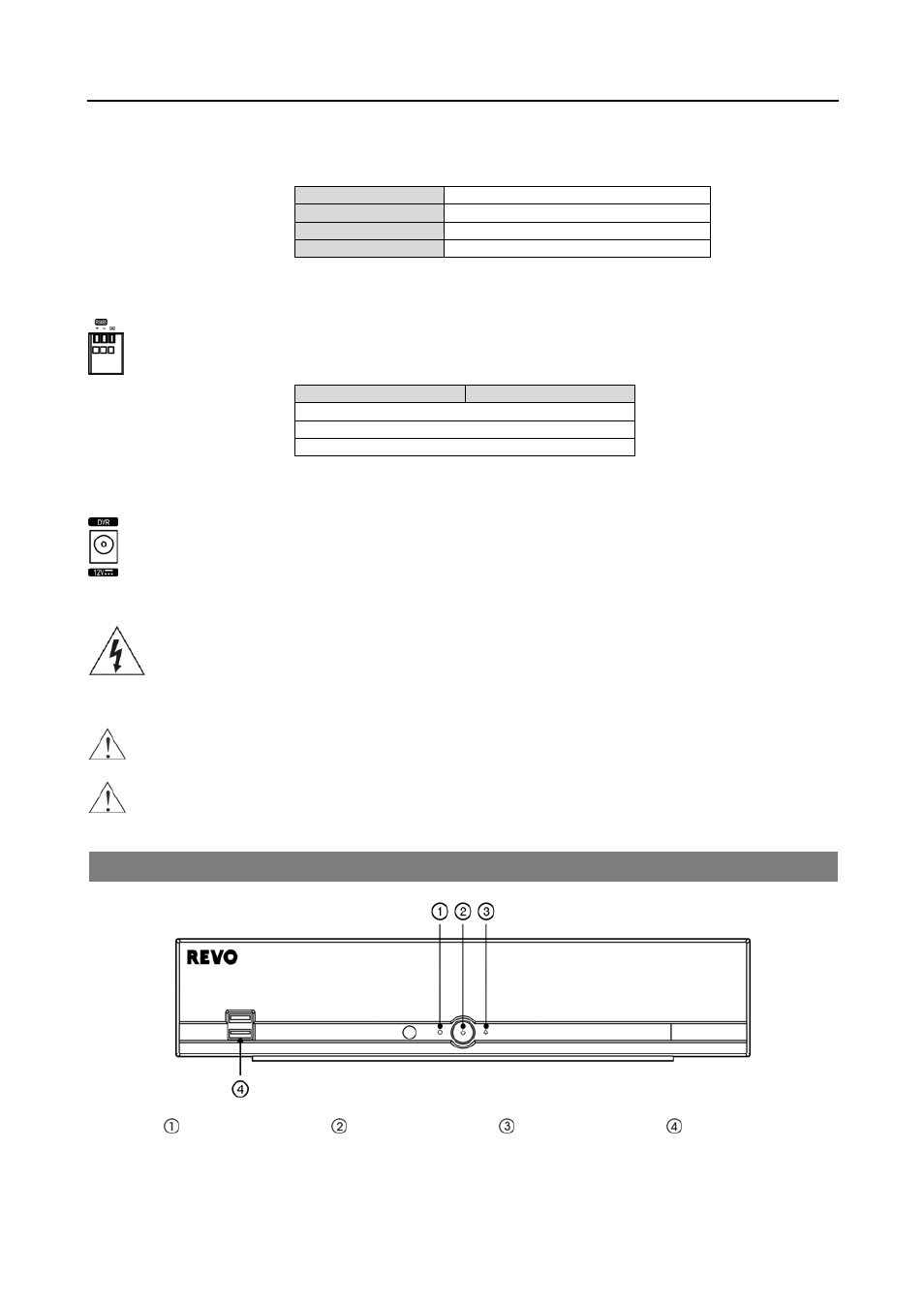
FRONT PANEL CONTROLS
HDD LED
Power LED
Alarm LED
USB Port
NOTE: The infrared sensor on the DVR is just to the left of the HDD LED. Make certain that nothing blocks the
sensor, or the remote control will not function properly.