KROHNE C95 CI EN User Manual
Page 15
S
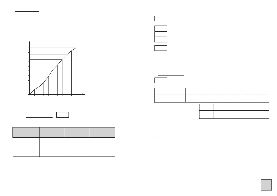
Programming :
d.in = 0 mA
F.in = 20 mA
nb = 9
d.disp = 0,000 m3 F.disp = 0,785 m3
Programming from A01 to A09 and from B01 to B09 according to table.
4.5.2 Voltage input
• Linear
: Features
0 2 4 6 8 10 12 14 16 18 20
0 0.1 0.2 0.3 0.4 0.5 0.6 0.7 0.8 0.9 1
20
18
16
14
12
10
8
6
4
2
0.11
0.04
0.20
0.29
0.39
0.49
0.59
0.67
0.75
0.79
volume
in m3
output (mA)
Y
X
input (mA)
height (m)
U
«
Caliber
Display
resolution
Input stage
resolution
Accuracy
-100 to +100 mV
-1 to + 1 V
-10 to +10 V
-300 to 300 V
± 1 digit
16 bits
0.05% of MR
• Unlinear :
(
see p13
)
Measurable limits : -5% to +5%
Example for caliber 1V : -1.1V to +1.1V
4.5.3 Instant value display :
Decimal point location for the instant value display
(4 decimals maximum).
Display corresponding to input down scale
Display corresponding to input full scale
Setting in display points of the ordinate for point Axx for
a special curve input (see unlinear input)
Expressed in display points.
− If display full scale > display down scale and if display ≤ cut off value,
then it is maintained at down scale.
− If display full scale < display down scale and if display ≥ cut off value,
then it is maintained at down scale.
•• Response time :
Digital filtering integration indice :
Programmable from 0 to 10; to be used in case of unsteady input.
2 cycle times, i.e. 240 ms must be added to obtain the maximum response
time.
Note : For the analog output response time, add 40ms to the values
shown in the table.
For the relays : add the time delay programmed on the alarms.
Point
d.diSP
F.diSP
bXX
Cut.oF
intEG
Typical response
time at 90%
120 ms 400 ms 600 ms
intEG
0
1
2
1 s
3
1.4 s
4
2 s
5
3 s
5 s
7.5 s
6
7
8
10 s
9
15 s
10