4 output voltage control, 1 front panel voltage control, 2 remote voltage control – KEPCO HSF 1500W Series (all models) Operator Manuals User Manual
Page 9: Output voltage control, Front panel voltage control, Remote voltage control, Front panel controls, indicators and test points, R. 3.4.1), R. 3.4.2). t, R 3.4)
HSF 1500W 022613
7
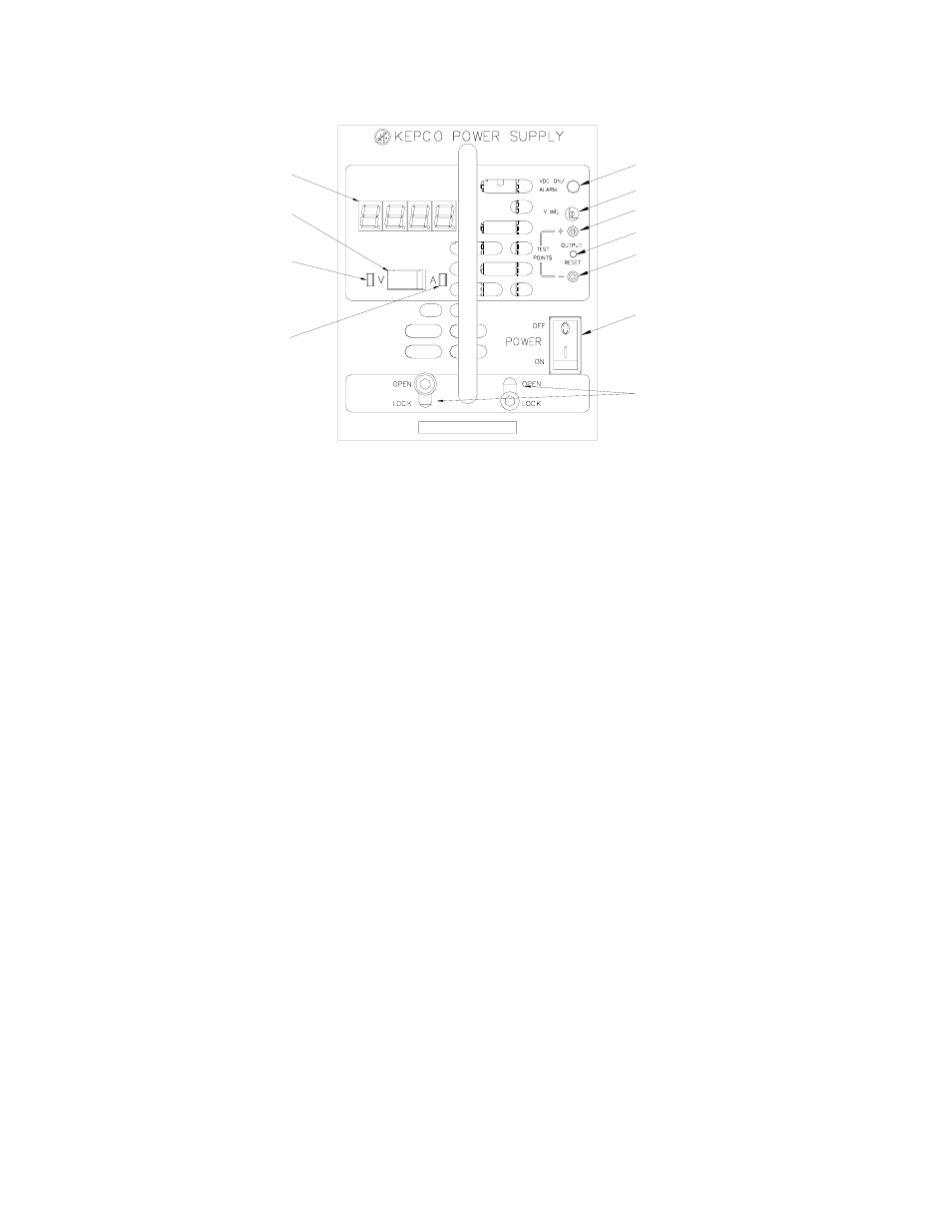
• OUTPUT RESET switch. Used to recycle power in the event of an alarm condition (see PAR. 3.7).
Not functional when remote on/off control is enabled (see PAR. 3.6).
• POWER ON/OFF switch. Applies power to the unit. CAUTION: Power must be OFF before unit is
removed from the rack adapter.
• Retaining Latches (2). Prevents inadvertent removal of unit from rack adapter (see PAR. 3.9)
• (M Suffix only) Voltage/Current meter: Monitors output voltage or current according to setting of
Meter Mode switch. NOTE: Voltage displayed may differ from voltage at the load depending on lead
length.
• (M Suffix only) Meter Mode slide switch: Set to V for display to show output voltage, set to A to show
output current.
• (M Suffix only) V indicator: Lights green to indicate meter is showing Volts.
• (M Suffix only) A indicator: Lights amber to indicate meter is showing Amperes.
FIGURE 5. FRONT PANEL CONTROLS, INDICATORS AND TEST POINTS
3.4
OUTPUT VOLTAGE CONTROL
Output Voltage can be controlled from either the front panel (PAR. 3.4.1) or externally using a
trimpot or voltage source (PAR. 3.4.2).
3.4.1 FRONT PANEL VOLTAGE CONTROL
Output voltage can be manually adjusted with the voltage adjustment control, Vadj (see Figure 5
for location) when DIP switches SW1 and SW2 (see Figure 4 for location) are configured as
shown in Figure 6A (factory default) To adjust voltage, first place the unit under an operating load.
Then monitor the (+) and (–) test points on the front panel with a precision voltmeter and turn the
voltage control to the desired operating value. Refer to Table 1 for the recommended Adjustment
Range.
3.4.2 REMOTE VOLTAGE CONTROL
For remote voltage control, set positions 1, 2 and 7 as shown in Figure 6B. This removes control
from the front panel Vadj control and allows the output voltage to be adjusted by either an external
trimmer pot (resistance) or by an external variable voltage source connected across the rack
adapter I/O connector pin 12 (RV, Remote Voltage) and pin 10 (–COM, Common) as shown in
Figure 7. At the rack adapter I/O connector use a shielded wire 6.6 feet (2M) maximum in length,
A (Amperes) indicator
(M Suffix only)
V (Voltage) indicator
(M Suffix only)
Meter Mode switch
(M Suffix only)
Voltage/Current Meter
(M Suffix only)
VDC ON/ALARM Indicator
V. ADJ Output Voltage Adjustment Trimmer
TEST POINT (+)
TEST POINT (-)
OUTPUT RESET switch
POWER ON/OFF switch
Retaining Latches
3043129