Figure 2. power rating vs. temperature, Table 3. power supply ratings and specifications, Power rating vs. temperature – KEPCO HSF 1500W Series (all models) Operator Manuals User Manual
Page 5: Power supply ratings and specifications, E 2 for, E 2), an
HSF 1500W 022613
3
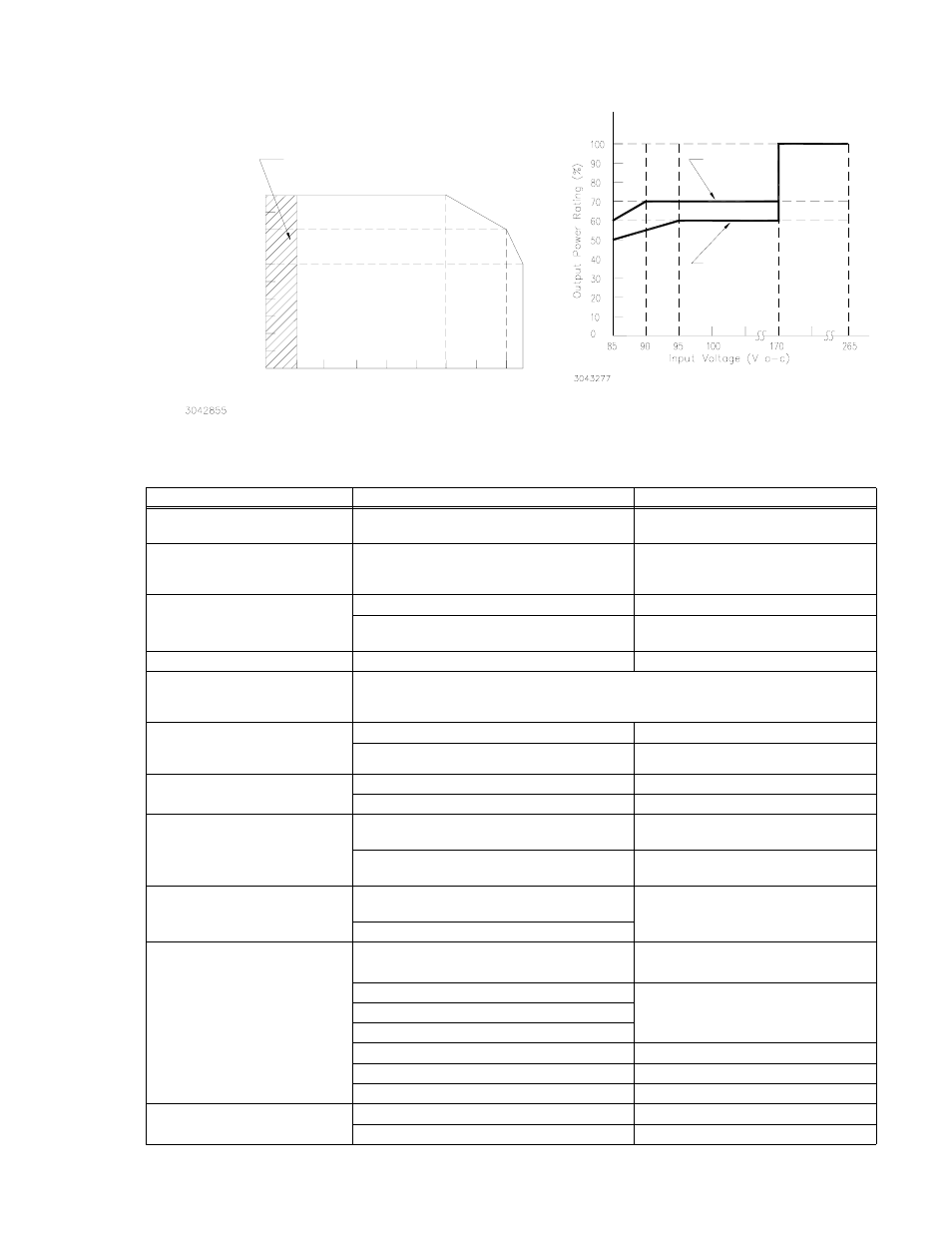
FIGURE 2. POWER RATING VS. TEMPERATURE
TABLE 3. POWER SUPPLY RATINGS AND SPECIFICATIONS
CHARACTERISTIC
SPECIFICATION
CONDITION/NOTES
Input Voltage
Nominal: 100-120V a-c, 200-240V a-c
Range: 85-264V a-c
0 to 100% load, -10 to 40°C
Input Source Frequency
Nominal: 50-60 Hz
Range: 47-440 Hz
0 to 100% load, -10 to 40°C
At 440 Hz leakage current exceeds
UL/VDE safety spec. limit.
Input Current: (Maximum Load At
25°C with Nominal Output Voltage)
13A rms max. (12A max. for 24V model)
100 - 120V a-c
10A rms max.
(8A rms max for 24V model)
200 - 240V a-c
Switching Frequency
140KHz
Forward Converter
Input Protection
A limiting resistor in series with a resistor fuse (and thyristor circuit) reduces start-up surge.
The internal power supply is protected against shorts by an input fuse. Fuse value 25.0A At
250 Volts
Input Surge cold start, interval > 30
sec ( First surge only, not including
current flow into EMI filter)
15A typ., 20A max. first surge
100 - 120V a-c
30A typ., 40 max. first surge
200- 240 V a-c
Leakage Current:
0.30mA typ., 0.75mA max.
120V a-c, 60Hz per IEC 950 and UL1950
0.60mA typ., 0.75mA max.
240V a-c, 60Hz per IEC 950 and UL1950
Power Factor
0.99 typical
100V a-c, max load, nominal output,
per EN 61000-3-2
0.95 typical
200V a-c, max load, nominal output
per EN 61000-3-2
Transient Recovery
excursion
characteristic
±4% maximum
50% to 100% load,
transient time >50
µ
sec
recovery time 1 ms maximum
Stabilization
Source Effect (min - max) ±0.1% Typical, ±0.2% Maximum
85 to 132V a-c, 190 to 264V a-c
Load Effect 24V Model: ±2.5% Typical, ±3.0% Maximum
0%-100% load change
36V Model: ±2.0% Typical, ±2.5% Maximum
48V Model: ±1.5% Typical, ±2.0% Maximum
Temperature Effect ±0.5% Typical, ±1.0% Maximum
–10° to 40°C
Combined Effect ±1.6% Typical, ±3.2% Maximum
Source, Load and Temperature
Time Effect 0.2% Typical, 0.5% Maximum
(8 hours at 25°C)
Start-up Time
300 msec Typical, 450 msec Maximum
100V a-c
250 msec Typical, 400 msec Maximum
200V a-c
THE POWER SUPPLY WILL STARTUP
BETWEEN -20 AND -10°C BUT MAY NOT
MEET PUBLISHED SPECIFICATIONS.
POWER RATING VS. TEMPERATURE
O
ut
pu
t P
o
w
e
r
R
at
in
g
(%
)
Ambient Temperature (°)
-10
0
10
20
30
40
50
60 65
-20
10
20
40
50
60
70
80
90
30
100(*)
POWER RATING VS. INPUT VOLTAGE
36 V MODEL
48 V MODEL
24V MODEL
NOTE: Safety agency approvals apply only to operation between
-10°C and 40°C.