9 retaining latches, Retaining latches, Correct and incorrect methods of load connection – KEPCO HSF 1500W Series (all models) Operator Manuals User Manual
Page 14
12
HSF 1500W 022613
3.9
RETAINING LATCHES
HSF 1200W/1500W series power supplies are provided with (2) retention latches located at each
side of the bottom edge of the front panel (see Figure 5). These latches work in conjunction with
the RA 19-4C rack adapters to prevent unauthorized or inadvertent module extraction from an
operating power system. The latch is engaged by loosening the cap-head screw approximately 1/
2 turn CCW (use 5/32” hex key) and sliding the latch down to the bottom of the slot, then retight-
ening the cap-head screw CW until snug. DO NOT OVERTIGHTEN! To release, follow the same
procedure, except lift the latch to the top of the slot. Be sure to move the latch completely up or
down to ensure full engagement and disengagement of the latching mechanism. When the HSP
power supply is not installed in its plug-in rack adapter, it is recommended that the latch be
secured in the open (up) position to prevent damage.
NOTE: Retaining latches must not be used to secure the HSF power supply in the rack
adapter for shipping purposes.
4.
LOAD CONNECTION
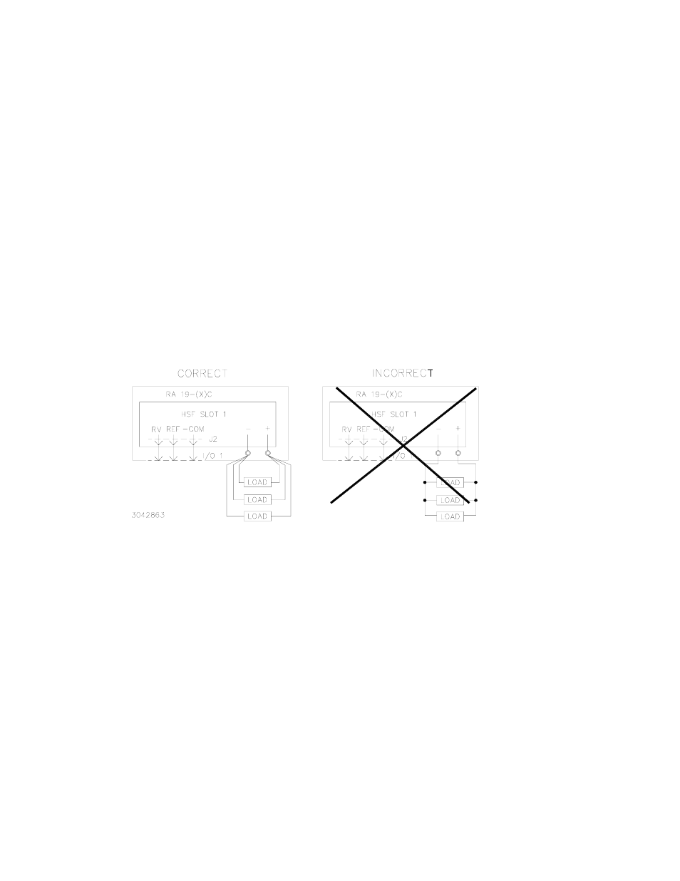
Connect the load to (+) and (–) terminals at the rear panel of the Rack Adapter. See Figure 12 for
the proper way to connect multiple loads.
FIGURE 12. CORRECT AND INCORRECT METHODS OF LOAD CONNECTION
5.
CONNECTING MULTIPLE POWER SUPPLIES
All connections to multiple HSF power supplies must be made via the I/O mating connectors at
rear of the Rack Adapter or by the Rack Adapter DIP switches. These connections, including the
configuration of the two internal HSF DIP switches, are described in the Rack Adapter Instruction
manual, and include:
• Using one power supply to control the output of multiple supplies.
• Using parallel master/slave configurations (for increased current or redundancy) where
the user either predetermines the master or allows the load to determine which is the
master. These configurations also cover the use of the Current Balancing feature of the
power supply. NOTE: Requires minimum of 10% load to operate properly.
• Using series configurations (for increased voltage).
• Using open-on-fail or close-on-fail alarm schemes with multiple power supplies.