5 current monitor (c and m suffix only), Current monitor (c and m suffix only), Dip switch settings for control of output voltage – KEPCO HSF 1500W Series (all models) Operator Manuals User Manual
Page 10
8
HSF 1500W 022613
for connection of REF (pin 2), RV (pin 12), and –COM (pin 10) to the trimmer control or external
voltage source.
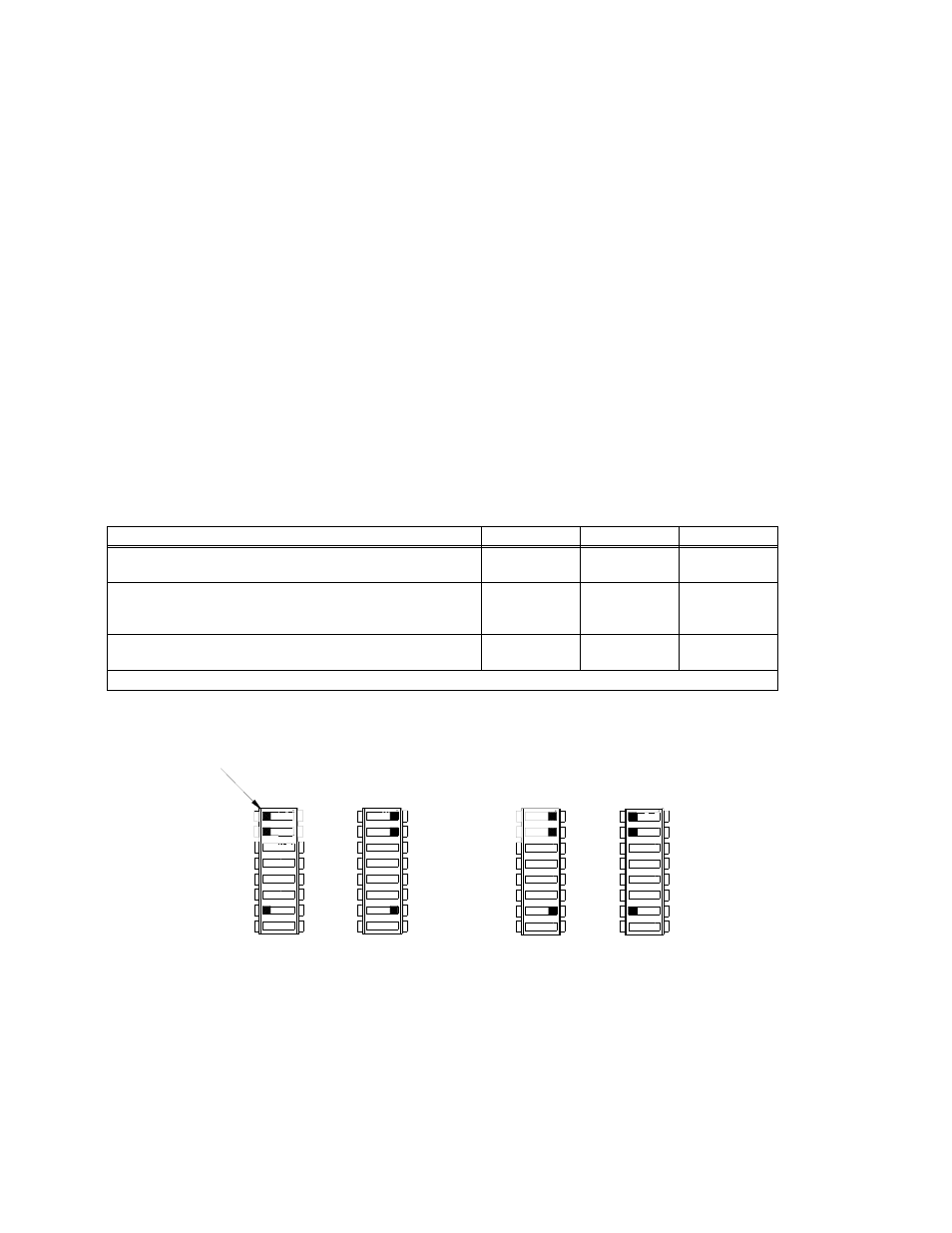
NOTE: If remote voltage control is not implemented, the factory default for positions 1, 2 and 7
of DIP switches SW1 and SW2 must be restored (Figure 6A).
It is possible that the overvoltage protection may be triggered if the output voltage is decreased to a
low level very quickly when the power supply is at a low load condition.
RESISTANCE: Connect the external trimmer as shown in Figure 7A. Suggested value for the trim-
mer control is 5K ohms. Referring to Figure 7 (A), R = 7.5K Ohms (M suffix: R = 5.6K Ohms) pro-
vides an output voltage adjustment range of from 70 to 130%. for the 24V model. R = 560 Ohms
provides an output voltage adjustment range of from 17 to 150%. for the 36V model. R = 10K
Ohms (M suffix: R = 7.5K Ohms) provides an output voltage adjustment range of from 70 to 115%
for the 48V model.
VOLTAGE. By adjusting an external 3.5 to 6.5V voltage source, the 24V model can be adjusted
from 70 to 130% of the nominal output. By adjusting an external 0 to 5.75V voltage source, the 36V
model can be adjusted from 17 to 150% of the nominal output. By adjusting an external 3.5 to 5.75V
voltage source, the 48V model can be adjusted from 70 to 115% of the nominal output. To ensure
proper operation of the alarm relay, meter (M suffix only) and LED indicators, do not adjust exter-
nal voltage below minimum listed in Table 4. Connect the voltage source across the RV and –COM
pins as shown in Figure 7B.
FIGURE 6. DIP SWITCH SETTINGS FOR CONTROL OF OUTPUT VOLTAGE
3.5
CURRENT MONITOR (C AND M SUFFIX ONLY)
Current monitor is via ±IMON assigned to pins of the RA 19-4C I/O connector (see Figure 1).
Monitored Output Current (Amps) = Voltage drop across Rs (Volts) x Rs (Ohms), where voltage
drop across Rs (see Table 2) is measured across ± IMON pins (requires millivoltmeter, range 0 to
200mV). Accuracy is ±3%; contact Kepco if greater accuracy is required. There is no isolation
between ±IMON, alarm circuit and d-c output.
TABLE 4. MINIMUM CONDITIONS FOR RELAY, METER AND LED OPERATION
MODEL
HSF 24-27
HSF 36-42
HSF 48-32
Minimum HSF output voltage required for relay, meter and LED
functioning (Volts d-c)
1
17
11
35
Minimum resistance of Limit resistor R (Figure 7A) in series with
5K ohm Trimpot to ensure proper operation of LEDs, meter and
relay (Ohms)
1
7.5K
560
10K
Minimum external voltage (Figure 7B) to ensure proper operation
of LEDs, meter and relay. (Volts d-c)
1
3.7
0.68
3.8
1 - If operating below minimums listed, see PAR. 3.8.2.2 to implement ±PF alarm signals to monitor power supply status.
OFF
SW1
3042875
COM 7
REF 1
RV 2
7
7
SW2
7 COM
1
ON
2
1
2
OFF
1 REF
2 RV
ON
SW1
SW2
7
7
1
2
OFF
ON
1
2
OFF
ON
USING Vadj CONTROL
FRONT PANEL VOLTAGE CONTROL
A
B
(FACTORY DEFAULT)
REMOTE VOLTAGE CONTROL
OR VOLTAGE SOURCE
USING EXTERNAL TRIMPOT
COM 7
REF 1
RV 2
2 RV
1 REF
7 COM
TAB