Figure 4. dip switch configuration, 2 front panel access, 3 keying – KEPCO HSF 1500W Series (all models) Operator Manuals User Manual
Page 8: Front panel access, Keying, Dip switch configuration, 4), which, Detail view
6
HSF 1500W 022613
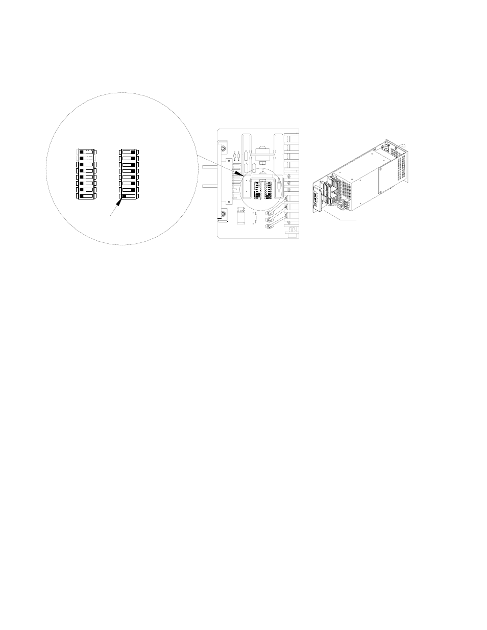
• Position 8 of SW1 either disables (default) or enables the visual alarm indication (see
PAR. 3.8.1).
FIGURE 4. DIP SWITCH CONFIGURATION
3.2
FRONT PANEL ACCESS.
The front panel provides a power ON/OFF switch controlling input power and a "VDC ON" indica-
tor which lights green when the unit is operating. If the unit is connected in a parallel configuration,
the indicator lights red if the unit shuts off automatically, or the POWER switch is set to OFF.
CAUTION: DO NOT repeatedly toggle the power ON/OFF switch as this may cause unit to
fault.
NOTE: The ON/OFF switch must be set to OFF before removing unit from rack adapter.
If remote on-off is not enabled (see PAR. 3.6), the OUTPUT RESET button restores output power
in the event that overcurrent or overvoltage protection has tripped, or thermal overload or fan mal-
function has occurred.
If remote voltage control (see PAR. 3.4.2) is not enabled, the front panel Vadj trimmer (see PAR.
3.4.1) provides adjustment of the output voltage within the limits specified in Table 1; test points
are available at the front panel for monitoring the DC output.
Figure 5 shows the location of all operating controls, indicators and test points followed by an
explanation of each.
3.3
KEYING
Keying of the power supply is established at the factory. The output voltage determines which key
pins are installed (see Figure 3, Detail A). When the proper holes in the rack adapter are blocked
by keying screws installed by the user, only a power supply of the correct voltage can be inserted
in the rack adapter slot. Refer to the RA 19-4C Manual for rack adapter keying instructions.
• VDC ON/ALARM indicator. Lights green when unit is operating. When enabled by DIP switch config-
uration, lights red to indicate loss of output voltage in parallel configuration only (see PAR. 3.8.1).
• V.ADJ Output voltage adjustment trimmer: Adjusts output voltage within limits specified in Table 2
(see PAR. 3.4.1). Not functional if remote voltage control is enabled (see PAR. 3.4.2).
• DC output test points (+, –): Connect to voltmeter to monitor output voltage.
NOTE: NOT ALL COMPONENTS SHOWN.
FACTORY DEFAULT SETTING:
- FRONT PANEL VADJ CONTROL
- RELAY ALARM SELECTED
- VISUAL ALARM DISABLED
- REMOTE ON-OFF DISABLED
SW2
OFF
3042858
+RC 3
-COM 7
N/A 8
-PF
+PF
-RC
5
6
4
RV
REF 1
2
ALARM LED DISABLE
3
3
3
+RC
7
7
8
8
5
6
4
5
6
4
7 -COM
SW1
8
5 +PF
-PF
6
-RC
4
OFF
1
2
ON
1
2
ON
1 REF
RV
2
SEE DETAIL VIEW
DETAIL VIEW
SW1
SW2
TAB